

Loading…
Loading…
Loading…
Eduqas GCSE Design and Technology · C600
Eduqas C600 · Systems Components and Ecological Footprint Check the specification (PDF) (opens in a new tab)
A mechanical transmission carries motion and force from an input to an output. For example, a motor can turn a shaft, while a belt or a set of gears transfers that rotation to another shaft. The input component is the driver; the component receiving its motion is driven.
A transmission can change the output’s rotational speed, direction or the position of its shaft. It can also change torque, the turning effect available at the shaft. A slower output can provide greater torque, which is useful when turning a heavy load. A faster output provides less torque. This is a trade-off, not a way of creating extra power; friction also causes losses in real mechanisms.
A pulley is a wheel with a groove around its rim. In a belt drive, a continuous belt runs around a driver pulley and a driven pulley. As the driver turns, friction between it and the belt moves the belt, which turns the driven pulley. This transfers rotary motion between separated shafts.
An open belt makes the two pulleys rotate in the same direction. Crossing the belt makes them rotate in opposite directions. V-belts run in matching grooves, helping the belt grip the pulley; cars use this type of drive.
Pulley size determines the speed change. The belt travels the same distance around each pulley in a given time, assuming it does not slip. A small pulley must therefore make more turns than a large pulley. A small driver turning a larger driven pulley reduces output speed; a large driver turning a smaller driven pulley increases it.
Belts are relatively quiet and can connect shafts that are some distance apart. However, they can slip under load, so their actual output speed may differ from the calculated speed.
Pulleys can also guide ropes for lifting. A single fixed pulley changes the direction of the pull, allowing a person to pull down to lift a load. A compound lifting arrangement, such as a block and tackle, shares the load between supporting rope sections and reduces the required pulling force. The trade-off is that more rope must be pulled through to lift the load a given distance.
Rotational speed means the number of complete turns made in a given time. It is commonly measured in revolutions per minute, or rpm. In the following equations, represents rotational speed and represents pulley diameter:
Rearranging gives:
Both diameters must use the same unit. The calculated output speed uses the same unit as the input speed.
For example, a 100 mm driver pulley turning at 2,000 rpm drives a 25 mm pulley. Its output speed is . The smaller driven pulley makes four turns for each turn of the driver.
To make the meaning of a ratio clear, this lesson uses velocity ratio as input rotational speed divided by output rotational speed:
For that pulley pair, , which can also be written as an input-to-output ratio of . A VR below 1 means the output is faster; a VR above 1 means the output is slower. VR has no unit because the matching speed units cancel.
A gear is a toothed wheel. When two gears mesh, their teeth engage so that one drives the other without the slipping possible in a friction belt drive. A set of connected gears is a gear train.
Ordinary external spur gears transfer rotation between parallel shafts. Two meshing gears rotate in opposite directions. At the mesh, the teeth carry motion in the same tangential direction, but the contact is on opposite sides of the two gear centres. For example, if the right-hand edge of the left gear moves downwards, it drives the left-hand edge of the right gear downwards too: the left gear turns clockwise and the right gear turns anticlockwise.
A small driver gear turning a larger driven gear reduces speed and increases available torque. Reversing their roles increases speed and reduces torque. Tooth counts give the speed relationship:
Therefore:
A 20-tooth driver meshing with a 60-tooth driven gear gives , or . The driver makes three turns for one output turn, so the output rotates at one-third of the input speed, in the opposite direction.
Adding an idler gear between the driver and final driven gear introduces a second reversal, making the input and final output rotate in the same direction. In a simple train, the idler’s tooth count does not change the overall speed ratio: that depends on the first driver and final driven gear.
A simple belt drive has one driver–driven pulley pair. A compound belt drive has successive stages. The driven pulley of the first stage shares an intermediate shaft with the driver pulley of the second stage. Because these two pulleys are fixed to the same shaft, they rotate together at the same speed, even if their diameters differ.
A compound gear train works in the same way. One gear receives motion at the intermediate shaft, while a second gear fixed to that shaft drives the next stage. Unlike an idler, this arrangement can produce a further speed change.
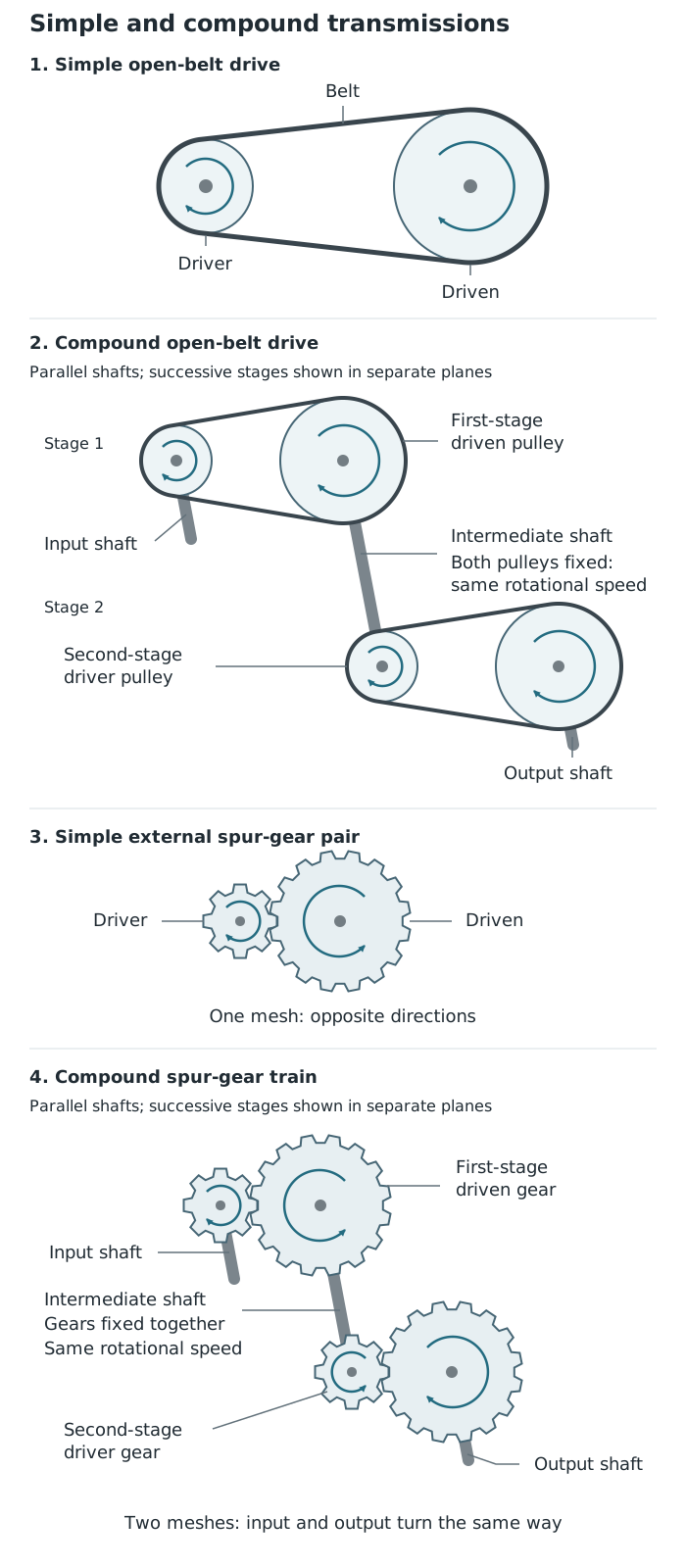
Compound transmissions link successive stages through components fixed to a shared intermediate shaft.
Calculate each stage ratio separately, then multiply:
For example, two successive stages with ratios of and give an overall reduction of . The output turns once for every six input turns. The output speed is found by dividing the input speed by the overall VR.
Compound systems can achieve a large reduction without needing one extremely large driven pulley or gear. However, extra stages mean more components and additional frictional losses. Rotation must still be checked stage by stage: every external gear mesh reverses direction, while each open belt preserves it.
A worm drive consists of a screw-shaped worm meshing with a toothed wheel. Their shafts are usually at right angles but do not intersect. The worm advances the wheel by a small amount on each turn, allowing a large speed reduction in a compact mechanism. This gives a slow output with greater torque, useful in mechanisms such as guitar tuning pegs and winches.
Many worm drives resist being driven backwards by the wheel, helping an output hold its position. This behaviour depends on the design: not every worm drive is self-locking, so it should not automatically be treated as a safety brake.
Bevel gears have cone-shaped toothed surfaces. A meshing pair transfers rotation between intersecting shafts, commonly at 90°. They are used in devices such as hand drills to turn the drive around a corner. Equal-sized bevel gears can change the axis of rotation without changing speed; unequal tooth counts produce a speed change.
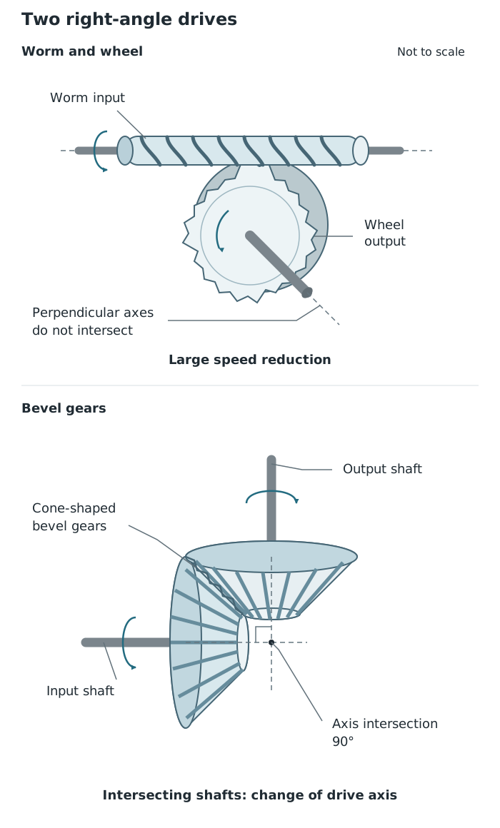
A worm drive gives a large reduction; bevel gears transfer rotation between intersecting shafts.
Both mechanisms can transmit motion around a right angle, but their main functions differ. Bevel gears are useful for changing the drive axis and can transmit drive in either direction. A worm drive is particularly useful when a large reduction and slow, controlled output are needed.
For pulley and belt drives, assuming no slip:
Identify the driver and driven components before substituting values. Use pulley diameters for belt drives and tooth counts for gears.
State which way round your ratio is written. Here, VR = input rotational speed ÷ output rotational speed; a VR greater than 1 means a slower output.
For a compound transmission, multiply the stage ratios. Components fixed to the same shaft have the same rotational speed.
Check rotation separately from speed: each external gear mesh reverses direction; an open belt preserves direction and a crossed belt reverses it.
Do not assume every worm drive is self-locking or that a speed reduction creates extra power.
It can see this note and what your specification asks for.
Answers are free with an account.
1 free note left this week
Get more free notesYour answer sets when this note comes back for review, or marks it complete.
Was this note helpful?
Log in to tell us whether it helped, or to report a problem.
Last updated
Driver
The input component that supplies motion to another component in a mechanical transmission.
Driven component
The output component that receives motion from a driver.
Velocity ratio
For a rotary transmission, the ratio of input rotational speed to output rotational speed: . It has no unit.
Rotational speed
The number of complete turns made per unit time, commonly measured in revolutions per minute (rpm).
Torque
The turning effect of a force about a shaft or pivot.
Pulley
A wheel with a groove around its rim that guides a belt or rope.
Belt drive
A system in which a moving belt transmits rotary motion between pulleys on separate shafts.
Gear
A toothed wheel that transmits rotary motion by meshing with another toothed component.
Compound transmission
A transmission with successive stages, including two components fixed to an intermediate shaft so that they rotate together.
Idler gear
An intermediate gear in a simple gear train that changes the final direction of rotation without changing the overall speed ratio.
Worm drive
A screw-shaped worm meshing with a toothed wheel, usually transmitting motion between shafts at right angles and providing a large speed reduction.
Bevel gear
A gear with teeth on a cone-shaped surface, used with another bevel gear to transmit rotary motion between intersecting shafts, commonly at 90°.
Put your knowledge into practice — try past paper questions for Design and Technology
Driver
The input component that supplies motion to another component in a mechanical transmission.
Driven component
The output component that receives motion from a driver.
Velocity ratio
For a rotary transmission, the ratio of input rotational speed to output rotational speed: . It has no unit.
Rotational speed
The number of complete turns made per unit time, commonly measured in revolutions per minute (rpm).
Torque
The turning effect of a force about a shaft or pivot.
Pulley
A wheel with a groove around its rim that guides a belt or rope.
Belt drive
A system in which a moving belt transmits rotary motion between pulleys on separate shafts.
Gear
A toothed wheel that transmits rotary motion by meshing with another toothed component.
Compound transmission
A transmission with successive stages, including two components fixed to an intermediate shaft so that they rotate together.
Idler gear
An intermediate gear in a simple gear train that changes the final direction of rotation without changing the overall speed ratio.
Worm drive
A screw-shaped worm meshing with a toothed wheel, usually transmitting motion between shafts at right angles and providing a large speed reduction.
Bevel gear
A gear with teeth on a cone-shaped surface, used with another bevel gear to transmit rotary motion between intersecting shafts, commonly at 90°.
For gears:
Using input speed ÷ output speed:
Use the diameter fraction for pulleys and the tooth-count fraction for gears. VR has no unit.