

Loading…
Loading…
Loading…
Eduqas GCSE Design and Technology · C600
Eduqas C600 · Systems Components and Ecological Footprint Check the specification (PDF) (opens in a new tab)
A control system receives information from inputs, processes it and operates outputs. A switch might report whether a door is closed; a sensor might report the temperature. The processing part decides whether to turn on a lamp, sound an alarm or run a motor.
Two ways to carry out this processing are logic gates, which apply fixed rules to digital signals, and microcontrollers, which follow a loaded program. Combining decisions allows a product to respond to several conditions rather than simply switching on whenever one input changes.
A digital signal has two states: LOW, represented by logic 0, and HIGH, represented by logic 1. In the simple circuit model, LOW is usually 0 V and HIGH is the supply voltage. The numbers describe signal states, not quantities of electricity.
An analogue signal, by contrast, can vary continuously over a range. A temperature-sensing circuit can provide an analogue voltage that changes as the temperature changes, whereas a digital input reports one of two states.
Before designing a control system, give each input a clear meaning. For example, if a door-switch input is HIGH when the door is closed, logic 1 means ‘closed’. The processing rule must use that meaning consistently.
A logic gate produces an output according to a particular rule. A truth table records its output for every possible input combination. Two digital inputs have four possible combinations.
An AND gate produces HIGH only when both inputs are HIGH. This suits a product that should operate only when two conditions are satisfied, such as a start request and a closed safety guard.
An OR gate produces HIGH when either input, or both inputs, are HIGH. It suits a warning that should operate when either of two sensors detects a problem.
An EOR gate, meaning exclusive OR and also called XOR, produces HIGH when its two inputs are different. Exactly one input must be HIGH: unlike OR, EOR produces LOW when both inputs are HIGH.
A NAND gate means NOT AND. First consider the AND result, then reverse it. Its output is therefore LOW only when both inputs are HIGH.
| Input B | Input A | AND output | OR output | EOR output | NAND output |
|---|---|---|---|---|---|
| 0 | 0 | 0 | 0 | 0 | 1 |
| 0 | 1 | 0 | 1 | 1 | 1 |
| 1 | 0 | 0 | 1 | 1 | 1 |
| 1 | 1 | 1 | 1 | 0 | 0 |
A NOT gate has only one input. It reverses that input, so it is also called an inverter.
| Input A | NOT output |
|---|---|
| 0 | 1 |
| 1 | 0 |
The output of one gate can become an input to another. This allows a system to combine conditions such as ‘B is HIGH and A is not HIGH’.
Consider a circuit in which input A passes through a NOT gate. Call the NOT output C. Inputs B and C then feed an AND gate, whose final output is Q.
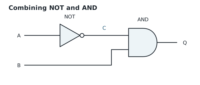
Find C by reversing A, then find Q by applying AND to B and C.
Complete C first by reversing A. Then find Q using B and C, because these are the actual inputs to the AND gate.
| Input B | Input A | Intermediate C: NOT A | Final Q: B AND C |
|---|---|---|---|
| 0 | 0 | 1 | 0 |
| 0 | 1 | 0 | 0 |
| 1 | 0 | 1 | 1 |
| 1 | 1 | 0 | 0 |
For the third row, A is LOW, so C is HIGH. B is also HIGH, so the AND output Q is HIGH. The whole circuit therefore produces HIGH only when B is HIGH and A is LOW.
The same approach works in reverse when designing a system: describe the required conditions, list all input combinations, decide the required output for each row, then select and connect gates that produce those results.
A microcontroller is a programmable integrated circuit into which software can be loaded to perform different tasks. Its program reads inputs, makes decisions and changes outputs. Changing the program can change the sequence or decision rules without rebuilding the processing circuit.
Microcontrollers have connection pins with particular functions. Some accept digital inputs; others can be configured for analogue or digital inputs. Some pins can be configured as inputs or outputs. The designer must choose a device with enough suitable connections and check its data sheet rather than assuming every pin can do every job.
Switch and sensing circuits provide signals to input pins. A suitable LED output can be controlled from an output pin with appropriate current limiting. Devices needing more power, such as motors or lamps, require an interface such as a transistor or MOSFET driver. The microcontroller supplies the control signal; the driver switches the load current.
A program can then be downloaded, tested with the actual input and output devices, and modified until the product behaves as intended.
A flowchart makes the order of a program visible. Arrows show the direction of execution. Rounded boxes mark Start and Stop, parallelograms show input/output actions, rectangles show processes such as delays, and diamonds show decisions with Yes and No routes.
For a warning lamp on a rubbish skip, the start switch is connected to input C5, the stop switch to input C1 and the lamp to output B0. The required sequence is to wait for the start switch, turn the lamp on for 2 seconds, turn it off for 1 second, and repeat until the stop switch is detected.
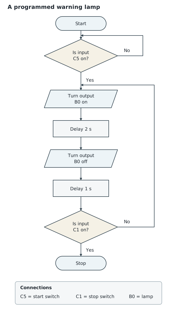
The start input is repeatedly tested; the stop input is checked after each complete flashing sequence.
At the first decision, ‘Is input C5 on?’, the No route loops back to the same test. The program repeatedly checks the start input rather than moving on. The Yes route begins the flashing sequence.
After the two delays and output changes, the program asks ‘Is input C1 on?’ A No answer repeats the flashing sequence; a Yes answer reaches Stop. This combines input testing, output control, time delays and repetition in one system.
The position of a test matters. Here the stop input is checked only after the complete on–off sequence. Pressing the stop switch during a delay does not cause an immediate response; the input must still be active when the program reaches its test.
A combined logic-gate circuit applies the rules built into its connections. A microcontroller applies instructions in software and can include sequences and delays as well as decisions. In either case, successful control depends on matching the input meanings, processing rules and output interfaces to the product’s requirements.
Find intermediate outputs first, then use them as the inputs to the next gate. A truth table includes every possible input combination.
For each logic question, identify what a HIGH input actually means: for example, ‘door closed’ or ‘door open’. Do not assume HIGH always means safe.
OR includes the case where both inputs are HIGH; two-input EOR does not.
Work through combined gates one stage at a time, recording intermediate outputs before finding the final output.
Read truth-table column headings carefully. The tables here place B before A.
When tracing a program, follow the arrows: an input is checked only when the program reaches its test.
It can see this note and what your specification asks for.
Answers are free with an account.
1 free note left this week
Get more free notesYour answer sets when this note comes back for review, or marks it complete.
Was this note helpful?
Log in to tell us whether it helped, or to report a problem.
Last updated
Microcontroller
A programmable integrated circuit into which software can be loaded to control input and output devices.
Digital signal
An electrical signal represented by two states: LOW, or logic 0, and HIGH, or logic 1.
Analogue signal
An electrical signal that can vary continuously over a range of values.
Logic gate
An electronic processing component that produces a digital output according to a particular rule applied to its input or inputs.
Truth table
A table showing the output for every possible combination of digital inputs.
AND gate
A logic gate whose output is HIGH only when all its inputs are HIGH.
OR gate
A logic gate whose output is HIGH when at least one input is HIGH.
EOR gate
An exclusive OR gate, also called XOR. With two inputs, its output is HIGH only when the inputs are different.
NOT gate
A one-input logic gate that reverses the input state: LOW becomes HIGH and HIGH becomes LOW.
NAND gate
A logic gate that produces the opposite output to an AND gate: its output is LOW only when all its inputs are HIGH.
Flowchart
A diagram of instructions and tests linked by arrows to show the order in which a program runs.
Put your knowledge into practice — try past paper questions for Design and Technology
Microcontroller
A programmable integrated circuit into which software can be loaded to control input and output devices.
Digital signal
An electrical signal represented by two states: LOW, or logic 0, and HIGH, or logic 1.
Analogue signal
An electrical signal that can vary continuously over a range of values.
Logic gate
An electronic processing component that produces a digital output according to a particular rule applied to its input or inputs.
Truth table
A table showing the output for every possible combination of digital inputs.
AND gate
A logic gate whose output is HIGH only when all its inputs are HIGH.
OR gate
A logic gate whose output is HIGH when at least one input is HIGH.
EOR gate
An exclusive OR gate, also called XOR. With two inputs, its output is HIGH only when the inputs are different.
NOT gate
A one-input logic gate that reverses the input state: LOW becomes HIGH and HIGH becomes LOW.
NAND gate
A logic gate that produces the opposite output to an AND gate: its output is LOW only when all its inputs are HIGH.
Flowchart
A diagram of instructions and tests linked by arrows to show the order in which a program runs.