

Loading…
Loading…
Loading…
Eduqas GCSE Design and Technology · C600
Eduqas C600 · Systems Components and Ecological Footprint Check the specification (PDF) (opens in a new tab)
A lever is a rigid bar that turns about a pivot called the fulcrum. The effort is the input force you apply; the load is the force you need to overcome or support. In a wheelbarrow, your hands supply the effort, the wheel’s axle acts as the fulcrum, and the weight of the contents provides the load.
The positions of these three parts determine what the lever does. Applying effort farther from the pivot gives it a greater turning effect. This is why a long handle can make lifting a load easier.
A lever’s class depends on which part lies between the other two.
| Class | Part in the middle | Example and arrangement |
|---|---|---|
| First class | Fulcrum | A seesaw has people on opposite sides of its pivot. Scissors have the pivot between the handles and cutting blades. |
| Second class | Load | A wheelbarrow’s load lies between the wheel’s axle and the handles. A nutcracker holds the nut between its hinge and the effort at its handles. |
| Third class | Effort | In tweezers, effort is applied between the joined end, which acts as the fulcrum, and the tips holding the load. |
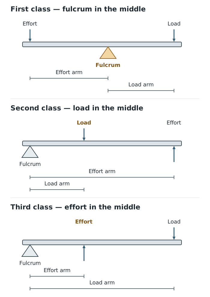
The component in the middle identifies the lever class; distances from the fulcrum determine the ideal force advantage.
A first-class lever can increase or reduce force, depending on the relative distances from the pivot. Moving the load closer to the pivot or applying effort farther away increases its force advantage.
In a second-class lever, the effort acts farther from the pivot than the load does. It therefore multiplies force in an ideal system. Long wheelbarrow handles and a load positioned close to the wheel reduce the effort needed.
In a third-class lever, the effort acts closer to the pivot than the load does. The output force is smaller than the input force, but the load moves farther for a given movement at the effort point. Tweezers use this arrangement to produce controlled movement and a gentle force at their tips.
Mechanical advantage, or MA, compares the load force with the force:
Both forces must use the same unit, normally newtons, N. Their units cancel, so MA has no unit.
An MA greater than 1 means the mechanism multiplies force. An MA of 1 means the output and input forces are equal. An MA below 1 means the output force is smaller than the input force.
A lever does not create energy. Where it multiplies force, the effort must move through a greater distance than the load moves. Real mechanisms also lose some energy through friction.
A moment is the turning effect of a force about a pivot:
The distance is measured from the pivot to the force’s line of action. For a horizontal lever with vertical forces, this is the horizontal distance from the pivot to where each force acts. Force in N multiplied by distance in m gives a moment in N m.
The principle of moments states that a balanced lever has equal total clockwise and anticlockwise moments. For a simple lever with effort and load producing opposing turning effects:
Here, is effort, is load, and and are their perpendicular distances from the pivot. In an ideal calculation, friction and the lever’s own weight are ignored unless included in the question.
To find an unknown effort, calculate the load’s moment and divide it by the effort’s perpendicular distance from the pivot:
The longer effort arm allows a smaller force to balance the load. To find an unknown load instead, rearrange to .
Rearranging the moments equation also gives a useful relationship for an ideal lever:
This connects the lever’s geometry directly to its force advantage.
A rack and pinion combines a circular gear, the pinion, with a straight toothed bar, the rack. Their teeth mesh. As the pinion rotates, its teeth push the rack along a straight path. Reversing the pinion’s rotation reverses the rack’s movement.
It can also work the other way: moving the rack can rotate the pinion. For example, a piston can push a rack, turning a pinion attached to an indexing table to move the table to its next position.
Unlike a mechanism that automatically moves back and forth, a rack continues moving in one direction while the pinion turns in one direction, until it reaches its travel limit.
A pawl and ratchet controls the direction of rotation. The ratchet is a wheel with shaped teeth; the pawl is a pivoted, spring-loaded catch that engages them.
In the permitted direction, the sloping teeth pass beneath the pawl, lifting it. The spring then pushes the pawl into the next gap. If the wheel tries to turn backwards, the pawl bears against a tooth and blocks movement. This allows forward rotation while preventing unwanted reversal. The pawl must be disengaged if reverse rotation is required.
This mechanism can also be used to advance a rotary indexing table in steps, positioning it ready for successive operations.
A crank and slider consists of a rotating crank, an off-centre crank pin, a connecting rod and a slider constrained to move along a straight guide.
As the crank rotates, its pin travels in a circle. The connecting rod transfers this movement to the slider, pushing it out and pulling it back. Continuous rotary input therefore produces reciprocating motion: repeated movement backwards and forwards along the same straight path.
The mechanism can work in reverse. A reciprocating piston can drive a crankshaft through a connecting rod, as in an engine. The connecting rod links the two parts throughout the movement rather than simply resting against a rotating surface.
A cam rotates while a follower tracks its outer profile. Changes in the distance from the rotation axis to the contact surface make the follower rise and fall. Gravity or a spring can keep the follower in contact as the surface falls away.
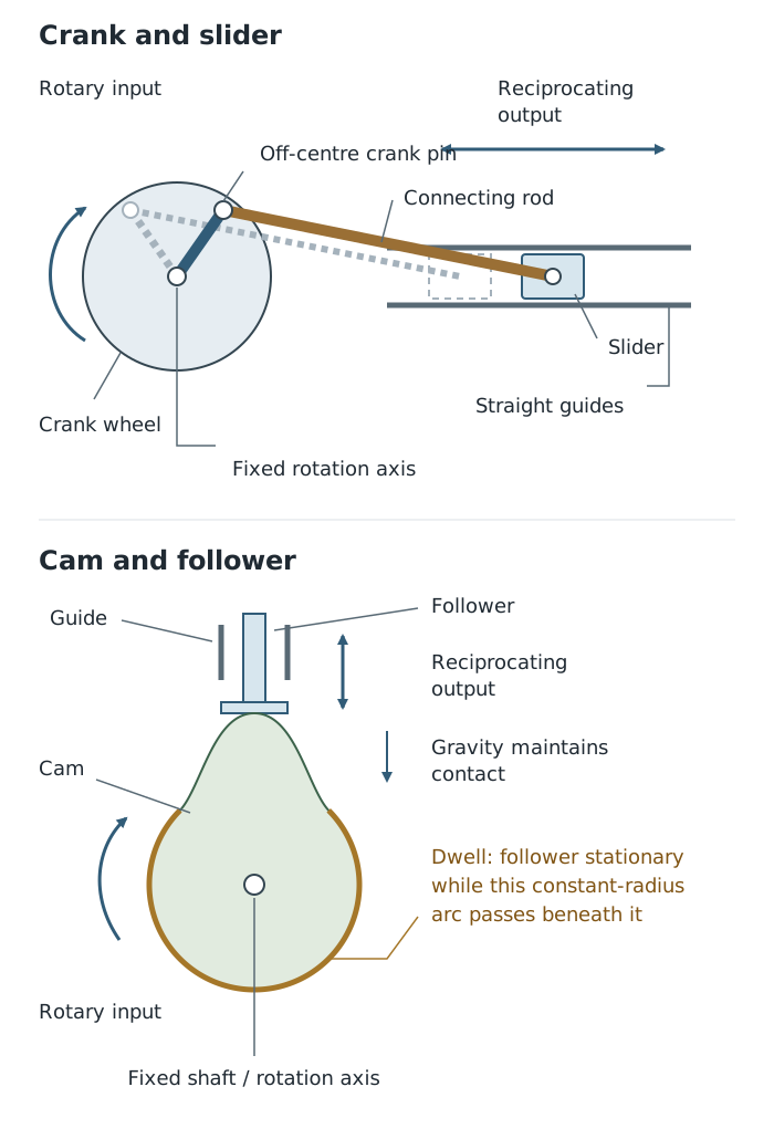
A connecting rod transmits the crank’s movement; a follower tracks the cam’s profile.
The cam’s profile determines the pattern of output movement. A circular cam mounted off-centre produces a repeated rise and fall. A profile with a constant-radius section can hold the follower still for part of the rotation; this stationary period is called a dwell. A snail cam can raise a follower gradually and then allow it to drop suddenly.
This makes cams useful where the timing and shape of movement matter. Engine cams control when valves open and close; snail cams can lift stamping-machine weights before releasing them to fall. Both a crank and slider and a cam can turn rotation into reciprocation, but a cam provides greater freedom to shape the rise, fall and dwell of the output.
Classify a lever by which part is in the middle: fulcrum, load or effort. Do not classify it by its appearance.
Measure each moment arm from the pivot, perpendicular to the force’s line of action—not between the effort and load.
Use consistent distance units. Forces are measured in N; moments can be expressed in N m. Mechanical advantage has no unit.
For a mechanism explanation, name the moving components and explain how their interaction produces the output motion.
Distinguish a crank and slider’s connected push–pull action from a cam follower tracking a rotating profile.
It can see this note and what your specification asks for.
Answers are free with an account.
1 free note left this week
Get more free notesYour answer sets when this note comes back for review, or marks it complete.
Was this note helpful?
Log in to tell us whether it helped, or to report a problem.
Last updated
Lever
A rigid bar that turns about a pivot to transmit force and movement.
Fulcrum
The pivot about which a lever turns.
Effort
The input force applied to a mechanism.
Load
The force that a mechanism must overcome or support.
Mechanical advantage
The ratio of output force to input force: . It has no unit.
Moment
The turning effect of a force about a pivot, calculated as force multiplied by the perpendicular distance from the pivot to the force’s line of action.
Principle of moments
For a balanced body, the total clockwise moment about a pivot equals the total anticlockwise moment about that pivot.
Rack and pinion
A mechanism in which a circular gear meshes with a straight toothed bar to convert rotary motion into linear motion, or vice versa.
Pawl and ratchet
A mechanism in which a pawl engages a toothed ratchet wheel to allow rotation in one direction while preventing reverse rotation.
Crank and slider
A mechanism linking an off-centre rotating crank to a guided slider through a connecting rod, converting rotary motion into reciprocating motion, or vice versa.
Cam
A rotating component whose profile controls the movement of a follower in contact with it.
Follower
The component that tracks a cam’s profile and moves as the cam turns.
Reciprocating motion
Repeated back-and-forth movement along a straight path.
Dwell
A period during a cam’s rotation when its follower remains stationary.
Put your knowledge into practice — try past paper questions for Design and Technology
Lever
A rigid bar that turns about a pivot to transmit force and movement.
Fulcrum
The pivot about which a lever turns.
Effort
The input force applied to a mechanism.
Load
The force that a mechanism must overcome or support.
Mechanical advantage
The ratio of output force to input force: . It has no unit.
Moment
The turning effect of a force about a pivot, calculated as force multiplied by the perpendicular distance from the pivot to the force’s line of action.
Principle of moments
For a balanced body, the total clockwise moment about a pivot equals the total anticlockwise moment about that pivot.
Rack and pinion
A mechanism in which a circular gear meshes with a straight toothed bar to convert rotary motion into linear motion, or vice versa.
Pawl and ratchet
A mechanism in which a pawl engages a toothed ratchet wheel to allow rotation in one direction while preventing reverse rotation.
Crank and slider
A mechanism linking an off-centre rotating crank to a guided slider through a connecting rod, converting rotary motion into reciprocating motion, or vice versa.
Cam
A rotating component whose profile controls the movement of a follower in contact with it.
Follower
The component that tracks a cam’s profile and moves as the cam turns.
Reciprocating motion
Repeated back-and-forth movement along a straight path.
Dwell
A period during a cam’s rotation when its follower remains stationary.
is the perpendicular distance from the pivot to the force’s line of action. For balance, total clockwise moments equal total anticlockwise moments.
For an ideal lever, . A longer effort arm or shorter load arm increases MA. Forces: N; moments: N m; MA: no unit.
| Mechanism | Essential action |
|---|---|
| Rack and pinion | Meshing circular gear and straight rack convert rotary motion into linear motion, or vice versa. |
| Pawl and ratchet | Spring-loaded pawl passes over teeth in one direction but engages a tooth to block reverse rotation. |
| Crank and slider | Off-centre crank and connecting rod drive a guided slider back and forth; reversible. |
| Cam and follower | Rotating profile controls follower rise, fall and dwell. |
A crank and slider uses a connected push–pull linkage. A cam uses contact with a profile to determine the movement pattern.