

Loading…
Loading…
Loading…
Eduqas GCSE Design and Technology · C600
Eduqas C600 · Prototyping Techniques and Assembly Check the specification (PDF) (opens in a new tab)
Plastic stock is material supplied in a standard form, such as sheet, bar, rod or tube. Making a prototype often means removing some of this material to obtain the required outline, contour or hole. This is called wastage: sawing removes material along a cut, drilling removes material to make a hole, and machining removes material with a cutting tool.
These methods can be used to cut and machine both thermoforming plastics and cured thermosetting plastics. The tool must suit the particular plastic, its thickness and the required shape. A method suitable for a thin sheet is not automatically suitable for a thick rod.
Accuracy depends on the whole sequence, not just the final machine operation: mark out carefully, hold the work securely, use the appropriate tool and check the finished feature against the intended dimensions.
Marking out transfers the design’s dimensions and shape onto the stock material. A steel rule measures short distances, a tape measure is useful for larger dimensions, and a try square helps mark lines at right angles to an edge. Mark the outline and the centres of any holes before cutting or drilling.
A sound reference edge helps keep related features aligned. For example, when making a rectangular plastic panel with two fixing holes, measure both hole positions from the same edges rather than from an uneven sawn edge.
Secure the work with a vice or clamps before cutting. Packing between the clamp jaws and the plastic protects its surface from marks. The grip must stop the material moving without damaging it. Unsupported or moving material makes accurate cutting difficult and can create a safety hazard.
Choose a saw according to the cut. A coping saw is useful for following curves, while a hacksaw or tenon saw can be used for suitable straight cuts. A bandsaw provides powered cutting; a fretsaw or jigsaw can cut more intricate outlines.
For hand sawing, clamp the sheet firmly and use smooth, even strokes with a suitable fine-toothed blade. Forceful sawing can splinter the plastic. Follow the marked outline, then check that the resulting shape and dimensions match the design.
Machining creates friction and heat. Excessive heat is particularly troublesome with thermoforming plastics because they can soften. Sharp cutting edges and a slow, steady feed during sawing help avoid poor cuts and excessive heating. A cut is complete when the required material has separated safely; inspect the edge for splintering, distortion and remaining waste before moving to the next operation.
Powered saws require the appropriate guards and trained supervision. Keep hands away from the blade and use a push stick where required, including when feeding suitable work through a bandsaw. Do not try to remove waste while the blade is moving.
A hand drill can produce holes, but a pillar drill gives more controlled positioning and movement. Its chuck holds the drill bit, and the bit is lowered into work secured on the table. The bit’s diameter determines the intended hole diameter: for example, a 6 mm hole requires a suitable 6 mm drill bit. The finished hole should still be checked, because tool condition and movement of the work can affect its accuracy.
Mark the hole position, fit and tighten the appropriate bit, and secure the plastic. Place suitable backing material beneath sheet plastic so that the drill can break through without damaging the table. A depth stop can control a hole that must not pass all the way through.
A jig can locate the work or guide the drill at the required position. A former can support a shaped piece so that it stays correctly positioned. These are especially useful when repeating the same hole pattern: the work is located consistently rather than measured again for every piece.
During drilling, the material must remain firmly clamped: if the drill catches, unsecured work can spin. Keep the drill sharp and control heat, withdrawing it as appropriate to clear waste from its flutes. Use eye protection, secure loose hair and clothing, and keep hands away from rotating parts. Stop the machine before adjusting the work or clearing waste by hand. Check the finished hole’s position, diameter and depth against the design.
A hole is not defined only by its diameter. Its shape and purpose determine how a fixing will work.
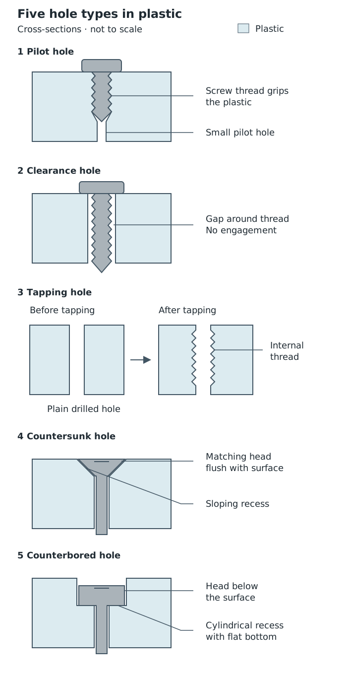
The hole’s profile must match its purpose: guiding, allowing passage, receiving a thread or recessing a fixing head.
The distinction matters when making a high-quality prototype. A screw head that should be flush needs the correct recess, while a part that should slide over a screw needs clearance rather than thread engagement. After machining, check that the intended fixing fits and that its head or thread sits as designed.
A lathe is used to turn material. In turning, the work rotates while a cutting tool removes material. Plastic rod can be held securely in a chuck as it rotates. This suits rounded forms made from stock such as plastic rod, rather than cutting a flat sheet outline with a saw.
A milling machine uses a rotating cutter to remove material. The work is clamped securely, and the rotating cutter and the work move relative to each other so that the cutter removes material to create a slot, or machine a flat face or edge. For example, a plastic component might need a slot to accommodate another part, while an edge might need machining to make it straight and accurately positioned. Unlike turning, milling rotates the cutting tool rather than the work.
Both processes depend on secure workholding, suitable sharp tools and control of heat. High-speed steel or carbide cutting tools can be used for machining plastics, with the choice and cutting conditions matched to the particular material and operation. There is no single speed or feed setting suitable for every plastic.
Cooling may be needed where frictional heat builds up, particularly during drilling. It is not necessary for every machining operation, and any cooling agent must be compatible with the plastic: some cutting fluids can cause stress cracking.
The operation is complete when the required feature reaches its specified dimensions, not merely when it looks approximately right. Check the turned form, slot width and depth, or flat face or edge against the design, and inspect for chipping or heat damage. Machine set-up and operation require training and supervision, secure workholding and appropriate guarding; stop the machine before adjustments or waste removal.
Computer-aided manufacture (CAM) uses computer instructions to control manufacturing equipment. A laser cutter is one example: it can follow a programmed outline to cut suitable plastic sheet. A blade-based cutting plotter is another example and can cut very thin material such as vinyl. Material suitable for a blade cutter is not necessarily safe for a laser cutter.
CAM connects a digital design to a physical part. A correctly prepared cutting path can be repeated without marking each outline by hand, but the material, thickness and machine settings must still suit the process. Computer control does not remove the need to check the design or inspect the result.
For laser cutting, first confirm that the material is approved for the particular machine. Acrylic is commonly approved, but not every plastic is suitable: PVC, including PVC vinyl, and ABS must not be assumed safe to laser cut. Follow the machine’s approved-material list rather than judging by appearance.
Prepare the cutting file, place the material in the machine and set the focus and cutting settings for its type and thickness. A supervised test cut helps establish settings that achieve the required cut without unnecessary heat damage.
Use the enclosed machine with its safety interlocks functioning and its extraction operating. Heating plastics can release harmful fumes, and laser cutting creates a fire risk. Monitor the process throughout: never leave a running laser cutter unattended. Follow the workshop’s emergency procedure if a problem occurs.
When cutting has finished, allow fumes to be extracted before opening the lid. Check for full separation, correct dimensions and unwanted heat damage before using the part. Do not force out a part that has not been cut through completely; have the settings and cutting process checked.
Link each tool choice to the task: for example, a coping saw can follow a curved outline, while a pillar drill produces a controlled hole of a chosen diameter.
Distinguish a pilot hole, which guides a screw, from a clearance hole, which lets the screw pass through without its thread gripping.
A countersink has a sloping recess; a counterbore has a flat-bottomed recess.
Include the milling machine’s ability to produce a flat face or edge, not just a slot.
CAM means computer-aided manufacture. Explain what the computer controls rather than simply saying that a machine is automatic.
It can see this note and what your specification asks for.
Answers are free with an account.
1 free note left this week
Get more free notesYour answer sets when this note comes back for review, or marks it complete.
Was this note helpful?
Log in to tell us whether it helped, or to report a problem.
Last updated
Wastage
Removing material from a piece of stock to produce the required shape, for example by sawing, drilling or milling.
Marking out
Transferring the required dimensions, outline and feature positions onto material before it is worked.
Jig
A device that locates work or guides a tool so that an operation can be carried out accurately and repeatedly.
Former
A shaped support or template used to establish or maintain a required shape or position during manufacture.
Pillar drill
A drilling machine with a drill mounted above a work table, allowing the rotating drill bit to be lowered into secured material.
Pilot hole
A small-diameter hole that guides a screw and helps prevent the material from splitting.
Clearance hole
A hole large enough for a screw or bolt to pass through without its thread engaging with the material.
Tapping hole
A hole drilled to a suitable diameter before a tap cuts an internal screw thread into it.
Countersunk hole
A hole with a flared, sloping recess at its opening that allows a matching screw head to sit flush with the surface.
Counterbored hole
A hole enlarged at its opening by a cylindrical, flat-bottomed recess.
Turning
A machining process in which material is rotated on a lathe and a cutting tool removes material to produce the required form.
Milling
A machining process using a rotating cutting tool to remove material, for example to create a slot or a flat face or edge.
CAM
Computer-aided manufacture: using computer instructions to control manufacturing equipment.
Put your knowledge into practice — try past paper questions for Design and Technology
Wastage
Removing material from a piece of stock to produce the required shape, for example by sawing, drilling or milling.
Marking out
Transferring the required dimensions, outline and feature positions onto material before it is worked.
Jig
A device that locates work or guides a tool so that an operation can be carried out accurately and repeatedly.
Former
A shaped support or template used to establish or maintain a required shape or position during manufacture.
Pillar drill
A drilling machine with a drill mounted above a work table, allowing the rotating drill bit to be lowered into secured material.
Pilot hole
A small-diameter hole that guides a screw and helps prevent the material from splitting.
Clearance hole
A hole large enough for a screw or bolt to pass through without its thread engaging with the material.
Tapping hole
A hole drilled to a suitable diameter before a tap cuts an internal screw thread into it.
Countersunk hole
A hole with a flared, sloping recess at its opening that allows a matching screw head to sit flush with the surface.
Counterbored hole
A hole enlarged at its opening by a cylindrical, flat-bottomed recess.
Turning
A machining process in which material is rotated on a lathe and a cutting tool removes material to produce the required form.
Milling
A machining process using a rotating cutting tool to remove material, for example to create a slot or a flat face or edge.
CAM
Computer-aided manufacture: using computer instructions to control manufacturing equipment.
Secure work, use guards and eye protection, control heat, and stop machinery before adjustments or waste removal. Check finished dimensions and surface quality.
For laser cutting: approved materials only, working enclosure/interlocks and extraction, continuous monitoring, and time for fumes to clear before opening.