

Loading…
Loading…
Loading…
Eduqas GCSE Design and Technology · C600
Eduqas C600 · Systems Components and Ecological Footprint Check the specification (PDF) (opens in a new tab)
An electronic control circuit often receives a small signal from a sensor or switch but needs to operate an output that requires much more current. A temperature-sensing circuit, for example, may need to control a heater through a relay. The sensing circuit makes the decision; a suitable process component turns that decision into an electrical signal capable of controlling the output.
Different process components do different jobs. A transistor can switch or amplify a signal, a timer can determine how long an output operates, and a comparator can decide whether a sensor voltage has crossed a chosen level. These functions can work together rather than being alternatives.
A transistor is a semiconductor component in which a small input controls a larger current. A common NPN transistor has three connections: base, collector and emitter. A small current entering the base controls a larger current flowing from collector to emitter.
In a simple NPN switching circuit, the output device is connected between the positive supply and the collector, while the emitter connects to 0 V. With no base current, the transistor is off and the output receives no current. With sufficient base current, the transistor is fully on, allowing current through the output. A resistor in the base connection limits the base current and protects the transistor.
The fully-on state is called saturation. For switching, the aim is to move between off and fully on rather than leave the transistor partly conducting. A partly-on transistor driving a substantial load can become hot because it has both current flowing through it and an appreciable voltage across it.
An output transducer converts electrical energy into another form: a motor produces movement and a loudspeaker produces sound. A transducer driver allows a small control signal to operate such a device when the control circuit cannot supply enough current itself. The transistor controls current from the power supply; the sensor or timer does not provide the energy needed by the load.
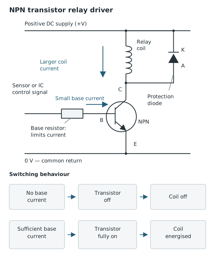
A small control current switches the larger relay-coil current. The diode protects the transistor when the coil switches off.
A transistor driver is useful because it responds quickly and has no moving switching contacts. However, it must be selected to handle the load’s current and voltage. It does not provide the electrical isolation offered by relay contacts. A transistor can therefore drive a relay coil while the relay switches a separate circuit.
When switching a motor, relay or solenoid, a protection diode is connected across the coil. During normal operation it is reverse-biased and does not conduct. When the transistor switches off, the collapsing magnetic field would otherwise produce a brief high voltage that could damage the transistor or IC. The diode provides a path for this temporary current.
Switching uses two output conditions: off and on. Amplification instead increases the size of a varying signal. Small changes in transistor base current can produce larger changes in collector current. With a suitable circuit, this can amplify a weak audio signal for an output such as a loudspeaker.
The extra energy comes from the power supply. The input signal controls how that energy reaches the output.
Gain describes how much a signal is increased. For a transistor, current gain compares collector current with base current:
This describes amplification while the transistor is operating in its amplifying region. It should not be used to assume unlimited output current: the transistor’s ratings and the surrounding circuit restrict what it can deliver. When used as a switch and fully saturated, the load and supply determine the collector current.
A capacitor stores electrical charge. Its charge-storage capability is called capacitance, measured in farads (F). Common electronic values are much smaller than a farad and are often written in microfarads:
A capacitor connected directly to a supply charges very quickly. Adding a resistor slows the flow of charge. The voltage across the capacitor rises rapidly at first, then more slowly as it approaches the supply voltage. When the capacitor discharges through a resistor, its voltage falls rapidly at first and then more slowly towards zero.
Increasing the resistance slows charging and discharging. Increasing the capacitance also increases the time taken because more charge must be stored for the same voltage change. Together, the resistor and capacitor form an RC timing network.
A changing capacitor voltage is not, by itself, a clean on/off timer output. It changes gradually, and drawing load current directly from the timing network can alter its behaviour. A processing circuit can respond to a chosen voltage level and produce a definite output change. A buffer or driver between the timing section and the load also reduces the effect of the load on the timing.
Some capacitors, including electrolytic capacitors, are polarised. Their positive and negative connections must be connected correctly, and their voltage rating must suit the supply.
An integrated circuit, or IC, contains many interconnected electronic components on one semiconductor chip. It provides a compact way to perform functions that would otherwise require several separate components. The 555 timer is an IC that can be connected for different timing functions.
A monostable has one stable output state. In the usual 555 monostable arrangement, its output is normally low. A brief trigger that changes from high to low makes the output go high for a set time, after which it returns low automatically. It therefore produces one timed pulse rather than a continuous sequence.
The pulse duration is controlled by an external resistor and capacitor:
Here is in seconds, is in ohms and is in farads. Increasing either or gives a longer pulse. A variable resistor can make the delay adjustable. A fixed resistor remains in series to limit current when the variable resistance is set very low.
A monostable is suitable when an output should operate for a fixed interval after an event—for example, a timed light triggered by a button. Component tolerances mean that the actual delay may differ from the calculated value, so a design needing accurate timing must account for this.
An astable has no stable output state. Its output repeatedly switches between low and high, producing a train of pulses. It is also called an astable multivibrator or pulse generator; a monostable is another form of multivibrator.
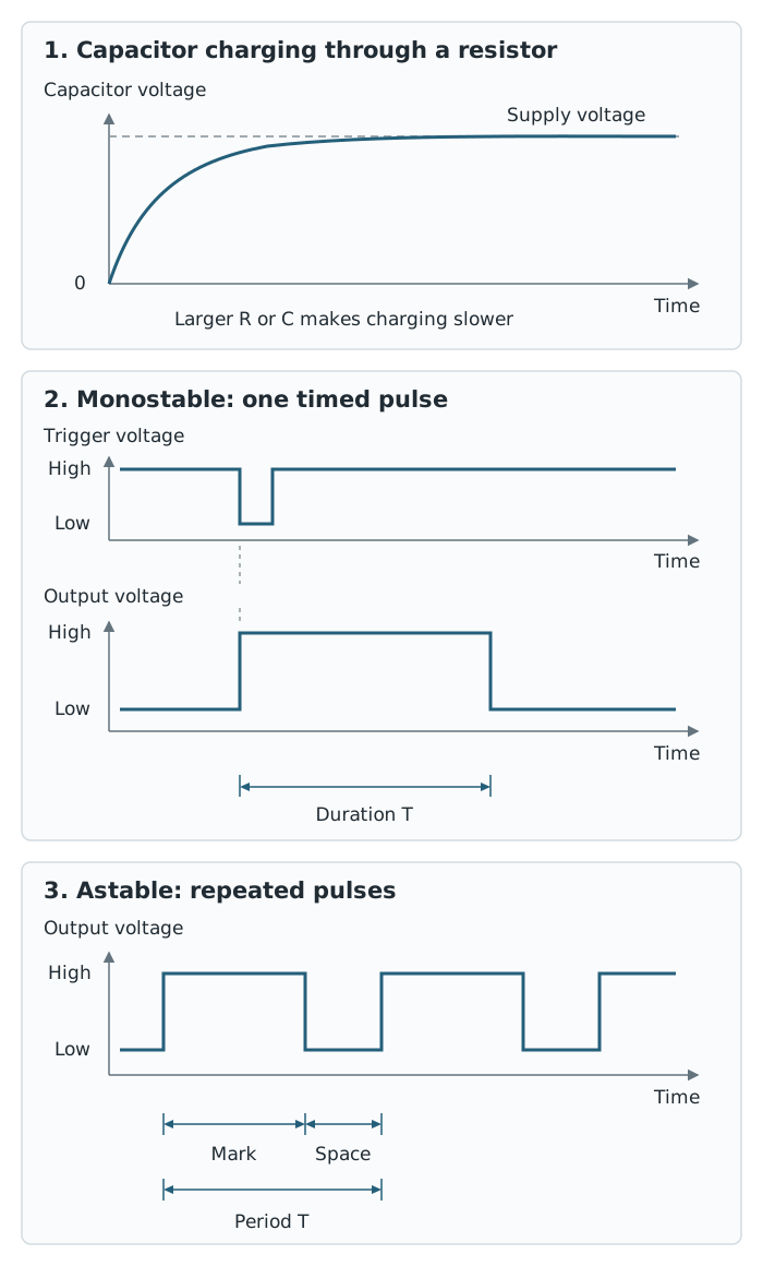
An RC network changes voltage gradually. A monostable produces one timed pulse; an astable repeatedly produces pulses.
The high interval is the mark and the low interval is the space. One complete cycle contains both. Its duration is the period, , and frequency is the number of complete cycles per second:
With in seconds, frequency is in hertz (Hz). On a voltage–time trace, measure one complete cycle between equivalent points, such as one rising edge and the next rising edge. Multiply the horizontal distance by the time-per-division setting before calculating frequency.
In a standard 555 astable circuit, two resistors, and , and a capacitor control the timing. Its approximate frequency is:
Use resistance in ohms and capacitance in farads to obtain frequency in Hz. Increasing the capacitor value or either resistance lowers the frequency. A variable timing resistor allows adjustment: a flashing indicator can flash faster or slower, while a pulse generator connected to a suitable sound output can alter its tone.
Repeated high and low outputs do not have to last equally long. The mark and space depend on the timing components. If the required output draws more current than the timer IC can safely supply, a transistor driver is still needed.
An operational amplifier, often shortened to op-amp, is an IC that amplifies the voltage difference between two inputs. These are the non-inverting input, marked +, and the inverting input, marked −. These marks identify the inputs; they are not the op-amp’s power-supply connections.
A 741 is an example of an op-amp IC. In an amplifier circuit, a small varying input can produce a larger varying output. Voltage gain is:
The two voltages must use the same units, so gain has no unit. A gain greater than one means that the output signal is larger than the input signal. The surrounding circuit sets a useful gain, while the power supply limits how large the output voltage can become. An amplifier cannot increase its output indefinitely.
An op-amp can also be used as a comparator. Rather than reproducing an enlarged version of a signal, it compares two voltages and produces a high or low output.
One input can receive a changing sensor voltage; the other receives a reference voltage representing the chosen switching level. If the voltage at the + input is greater than the voltage at the − input, the output goes towards its high level. If the − input voltage is greater, the output goes towards its low level. Swapping the input connections reverses the response.
In a temperature-control system, a thermistor potential divider provides the sensor voltage. A second divider provides the reference, which can be adjusted to select the switching temperature. The comparator output can control a transistor, which drives a relay for the heater.
The circuit can be arranged so that the heater switches on when the temperature is too low and off when it rises above the chosen level. The sensor then detects the temperature resulting from the heater’s action. This is feedback: the system’s output affects the condition being measured, and that measurement controls the next action.
A thyristor, also called a silicon controlled rectifier or SCR, is a semiconductor switch with three connections: anode, cathode and gate. A trigger at the gate starts conduction between the anode and cathode when the circuit is suitably supplied.
Unlike an ordinary transistor switch, a thyristor can remain conducting after its trigger disappears. This is latching. It is useful for an alarm that must stay active even if the event that triggered it was brief.
To reset the latch, the main current through the thyristor must be interrupted or reduced sufficiently—for example, by opening a switch in the supply path. Simply removing the gate signal does not reset it.
The choice follows the behaviour wanted: a transistor can follow a continuing control signal, a monostable gives a single timed interval, an astable gives repeated pulses, and a thyristor keeps an output on until it is deliberately reset.
Distinguish switching from amplification: a switch selects on or off; an amplifier increases a varying signal.
A transistor driver controls current supplied by the power supply. It does not create energy or make the sensor supply the load current.
For timing calculations, convert resistance to Ω and capacitance to F unless you deliberately use a compatible shortcut: MΩ with µF gives seconds in T = 1.1RC.
An astable’s period includes both the high and low times. Use the period in seconds when calculating frequency in Hz.
For a comparator, identify which voltage reaches the + input and which reaches the − input before deciding the output state.
Removing a thyristor’s gate signal does not normally switch it off: explain how the main current is interrupted.
It can see this note and what your specification asks for.
Answers are free with an account.
1 free note left this week
Get more free notesYour answer sets when this note comes back for review, or marks it complete.
Was this note helpful?
Log in to tell us whether it helped, or to report a problem.
Last updated
Transistor
A semiconductor component in which a small input controls a larger current; it can act as a switch, amplifier or output driver.
Amplifier
A circuit that increases the size of a varying electrical signal using energy from a power supply.
Gain
The ratio of an amplifier’s output signal to its input signal. Voltage gain is ; current gain compares output current with input current.
Transducer driver
A circuit that allows a small control signal to operate an output transducer requiring a larger current.
Integrated circuit
A component containing many interconnected electronic components on a semiconductor chip to perform a circuit function.
Capacitor
A component that stores electrical charge; charging or discharging it through a resistor provides a changing voltage for timing.
Monostable
A timing circuit with one stable output state that produces a single timed pulse when triggered.
Astable
A timing circuit with no stable output state that repeatedly switches between high and low outputs.
Multivibrator
An electronic circuit that generates pulses by switching between output states; monostable and astable circuits are forms of multivibrator.
Operational amplifier
An integrated-circuit amplifier that amplifies the voltage difference between its non-inverting (+) and inverting (−) inputs.
Comparator
A circuit that compares two input voltages and changes its output state according to which voltage is greater.
Thyristor
A semiconductor switching component, also called a silicon controlled rectifier (SCR), that can remain conducting after its gate trigger has been removed.
Latching
A switching action in which an output remains on after the initiating signal has ended, until it is reset.
Put your knowledge into practice — try past paper questions for Design and Technology
Transistor
A semiconductor component in which a small input controls a larger current; it can act as a switch, amplifier or output driver.
Amplifier
A circuit that increases the size of a varying electrical signal using energy from a power supply.
Gain
The ratio of an amplifier’s output signal to its input signal. Voltage gain is ; current gain compares output current with input current.
Transducer driver
A circuit that allows a small control signal to operate an output transducer requiring a larger current.
Integrated circuit
A component containing many interconnected electronic components on a semiconductor chip to perform a circuit function.
Capacitor
A component that stores electrical charge; charging or discharging it through a resistor provides a changing voltage for timing.
Monostable
A timing circuit with one stable output state that produces a single timed pulse when triggered.
Astable
A timing circuit with no stable output state that repeatedly switches between high and low outputs.
Multivibrator
An electronic circuit that generates pulses by switching between output states; monostable and astable circuits are forms of multivibrator.
Operational amplifier
An integrated-circuit amplifier that amplifies the voltage difference between its non-inverting (+) and inverting (−) inputs.
Comparator
A circuit that compares two input voltages and changes its output state according to which voltage is greater.
Thyristor
A semiconductor switching component, also called a silicon controlled rectifier (SCR), that can remain conducting after its gate trigger has been removed.
Latching
A switching action in which an output remains on after the initiating signal has ended, until it is reset.
Monostable: one stable state; a trigger produces one timed pulse.
Astable multivibrator: no stable state; continuous high/low pulses.
Use Ω and F for seconds and Hz. Period = mark + space. Increasing timing resistance or capacitance lowers frequency. Variable resistance makes timing adjustable.
Gate trigger → conduction continues after trigger ends. Reset by interrupting the main current. Useful when an alarm must remain on until deliberately reset.