

Loading…
Loading…
Loading…
Eduqas GCSE Design and Technology · C600
Eduqas C600 · Systems Components and Ecological Footprint Check the specification (PDF) (opens in a new tab)
An electronic system combines components to perform a task. It might detect a change in the surroundings, respond to a person pressing a button, or operate a moving part. A sub-system is a functional part of that larger system: a light-sensing unit, for example, can be one part of an alarm.
A useful way to understand a system is to separate it into input, process and output blocks. The input detects a condition or receives an instruction. The processing stage uses that electrical signal to control what happens next. The output produces the required action, such as light, sound or movement. Arrows between blocks show the direction in which signals pass; they are not a complete wiring diagram.
Consider an alarm designed to sound when light falls on a sensor. Its input is a light-sensing unit, its processing stage is a transducer driver, and its output is a buzzer. For a fan that switches on when a room becomes too warm, the corresponding blocks are a temperature-sensing unit, a transducer driver and a motor.
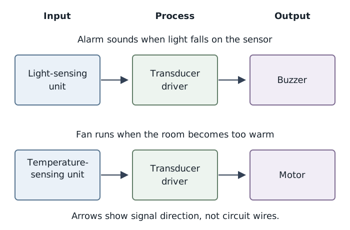
Different inputs and outputs can use the same functional pattern: sensing, driving and action.
The driver matters because a sensing unit often cannot supply enough current to operate an output directly. It allows a relatively small control signal to control the current needed by the output. Recognising that need is part of designing the system, even before choosing the detailed processing circuit.
Voltage is the potential difference between two points, measured in volts (V). It describes how much energy is transferred per unit charge. Current is the rate of flow of electric charge, measured in amperes (A). Resistance is opposition to current, measured in ohms (Ω).
For an ohmic component at constant temperature, these quantities are related by Ohm’s law:
Here, is the voltage across the component, is the current through it and is its resistance. Rearranging gives:
At a fixed voltage, increasing resistance reduces current. At a fixed resistance, increasing voltage increases current. These relationships explain why a resistor can protect another component from excessive current.
Resistance values can be written in larger units: and . Similarly, .
A fixed resistor provides a chosen resistance. A variable resistor allows that resistance to be adjusted, so the current can be set more precisely. When used to limit the current through a lamp, the resistor is connected in series with the lamp: the same current passes through both components.
A filament lamp has voltage and current ratings. Exceeding them can overheat and damage its filament. For example, a lamp rated at 6 V and 0.06 A has a resistance of about 100 Ω at its working temperature, since . A filament’s resistance changes with temperature, so this working value should not be treated as a fixed resistance under every condition.
To use that lamp with a 12 V supply, a series resistor can take the additional voltage. At the intended current of 0.06 A, a 100 Ω resistor has 6 V across it, leaving 6 V across the lamp. The extra resistance prevents the lamp from receiving the full supply voltage.
For a 2.5 V, 0.25 A lamp operating from a 6 V supply, the resistor must take . Its required resistance is therefore:
This is the resistance needed to drop the excess voltage at the lamp’s rated current. If the available preferred values are 13 Ω and 15 Ω, 15 Ω is the safer choice: it reduces the current slightly and makes the lamp a little dimmer. Choosing 13 Ω would allow more current than intended and put greater strain on the filament.
Colour bands identify a resistor’s nominal resistance and tolerance. For a four-band resistor, the first two bands give the two significant digits, the third is a multiplier, and the fourth gives the tolerance. The tolerance band is usually separated from the other three, helping you identify the reading direction.
| Colour | Digit | Multiplier |
|---|---|---|
| Black | 0 | ×1 |
| Brown | 1 | ×10 |
| Red | 2 | ×100 |
| Orange | 3 | ×1000 |
| Yellow | 4 | ×10 000 |
| Green | 5 | ×100 000 |
| Blue | 6 | ×1 000 000 |
| Violet | 7 | ×10 000 000 |
| Grey | 8 | ×100 000 000 |
| White | 9 | ×1 000 000 000 |
| Gold | — | ×0.1 |
| Silver | — | ×0.01 |
For the fourth band, red means ±2%, gold means ±5% and silver means ±10%. The same colour can have different meanings in different band positions: gold in the third position means divide by 10, whereas gold in the fourth position gives the tolerance.
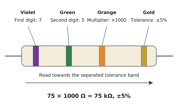
The first two bands give 75; the orange multiplier converts this to 75 kΩ.
For example, violet–green–orange–gold means 7, 5, multiplied by 1000, with ±5% tolerance:
The actual resistance may be up to 5% above or below the stated value. The bands describe a nominal value, not a guarantee that every resistor has exactly that resistance.
Brown–grey–black–silver means 1, 8, multiplied by 1, with ±10% tolerance. Its nominal resistance is therefore 18 Ω. Black as the multiplier means multiply by 1, not by zero.
To work backwards from a resistance to its bands, first express the value in ohms, separate the first two significant digits, then find the multiplier needed to restore the full value. Finally, add the tolerance band.
A switch controls an electrical connection. Open contacts do not conduct; closed contacts conduct. The letters in a switch name describe its contact arrangement, not whether it is operated by a toggle, slider or rocker.
| Switch | Contact arrangement and action | Suitable use |
|---|---|---|
| SPST: single pole, single throw | One contact set providing simple on–off control | Switching a circuit’s supply on or off |
| SPDT: single pole, double throw | One common contact changes between two conducting paths | Selecting either a red lamp or a green lamp |
| DPDT: double pole, double throw | Two changeover contact sets operated together | Reversing a motor’s polarity when appropriately wired |
| Push-to-make | Normally open; pressing closes the contacts, releasing opens them | A doorbell button |
| Push-to-break | Normally closed; pressing opens the contacts, releasing closes them | Interrupting a circuit while the button is held |
| Reed | A nearby magnet operates the contacts; a standard normally open version closes when the magnet approaches | Detecting whether a door is closed |
| Tilt | Tilting the switch changes whether its internal contacts are connected | Detecting an object’s orientation |
Push-to-make and push-to-break switches have momentary action: they return to their normal state when released. In contrast, an ordinary on–off toggle remains in the selected position.
Select switches for both their action and their electrical ratings. Their contacts must be suitable for the voltage and current being switched. A reed switch’s glass body is fragile and needs careful handling. Older tilt switches may contain poisonous mercury and should not be opened or used for classroom construction.
A light-dependent resistor, or LDR, changes resistance with light intensity. In darkness its resistance is high; as more light falls on it, its resistance decreases. This makes it useful as part of a light-sensing input unit.
The change is non-linear: resistance falls rapidly at first, then more slowly as light intensity increases. On a graph with light intensity on the horizontal axis and resistance on the vertical axis, this produces a falling curve that gradually becomes flatter, rather than a straight line.
A thermistor changes resistance with temperature. An NTC thermistor has a negative temperature coefficient: its resistance decreases as it gets warmer and increases as it gets colder. It can therefore provide the input for a temperature-controlled fan or a frost warning system. Thermistors do not all behave alike; a PTC thermistor has the opposite resistance–temperature relationship.
A simple moisture sensor, or moisture probe, uses two exposed conductive contacts, such as copper contacts, separated by a gap. When dry, very little current passes between them. Moisture bridging the contacts allows current to flow, so the resistance across the probe falls as it gets wetter. This provides an analogue input for monitoring soil moisture or triggering a rain alarm. For example, a waterlogging indicator can use the probe’s signal to switch on an LED in wet soil or grass and leave it off when dry.
These sensors change resistance, but the processing stage usually needs a changing voltage signal. A potential divider connects the two ideas.
A potential divider consists of two resistances connected in series across a supply. Call the upper resistance , connected towards the positive supply, and the lower resistance , connected towards 0 V. Take the output from their junction, measured relative to 0 V. The output is therefore the voltage across .
The supply voltage is shared between the two resistances. Equal resistances share it equally: two 1 kΩ resistors across a 9 V supply give a 4.5 V output. The resistance taking the greater share of the total resistance also takes the greater share of the supply voltage.
Replace one resistance with an LDR or thermistor and the output changes with the surroundings. The sensor’s position determines the direction of that change:
| Sensor position | Change in condition | Effect on output voltage |
|---|---|---|
| LDR as upper resistance | More light → lower LDR resistance | Output rises |
| LDR as lower resistance | More light → lower LDR resistance | Output falls |
| NTC thermistor as upper resistance |
For example, with an LDR above the junction and a fixed resistor below it, brighter light reduces the upper resistance. The lower resistor then takes a larger fraction of the supply voltage, so the output rises. Swapping the components reverses the response.
A conductive moisture probe can replace the LDR in the same arrangement. As the probe gets wetter, its resistance falls: placing it above the junction makes the output voltage rise, while placing it below the junction makes the output fall. A moisture-sensing unit arranged to give a rising output with increasing moisture can supply the signal for a rain alarm’s buzzer.
The other resistance can be adjustable rather than fixed. Adjusting it changes the output voltage at a particular light level or temperature, allowing the complete control system’s sensitivity or switching point to be set. The divider supplies the sensing signal; it does not necessarily supply enough current to operate a motor or alarm directly.
A relay is an electrically operated switch. Current through its coil produces a magnetic field, which attracts a movable metal armature and changes the position of the switch contacts. When the coil is no longer energised, the contacts return to their resting position.
A changeover relay has three contact terminals: COM (common), NC (normally closed) and NO (normally open). With the coil unpowered, COM connects to NC. When the coil is energised, COM disconnects from NC and connects to NO. A simpler normally open relay just closes its contact pair when energised.
The coil circuit and the contact circuit are electrically separate: movement transfers the switching action between them. This allows a low-voltage control circuit to switch a separate load, potentially requiring a different voltage or a larger current. For example, a temperature-sensing system can operate a relay that switches a fan. Both the coil and the contacts must have suitable ratings; the sensor may need a driver to supply the coil current.
This separation does not make mains construction safe for students. Classroom relay circuits should use approved low-voltage supplies; mains switching requires appropriately designed equipment and qualified supervision.
An output device turns an electrical signal into a useful physical action. Choose it from the product’s purpose, rather than simply from the components available.
| Output | Action and suitability | Example application |
|---|---|---|
| Lamp | Produces light, with heat also generated | Illumination |
| LED | Produces light when correctly connected and supplied with a suitable current | A visible status indicator |
| Buzzer | Produces an audible tone; an active buzzer includes circuitry to generate the sound | An audible alarm |
| Piezo sounder | Produces sound from a changing electrical signal; suited to simple tones and bleeps | A timer’s alert |
| Loudspeaker | Reproduces sound from a varying electrical signal; suitable for speech and music as well as tones | A spoken announcement |
| Siren |
A motor and a solenoid are not interchangeable: a fan needs rotation, while a latch needs a straight movement. Similarly, a piezo sounder is useful for a simple alert but is not a good choice for clear speech or music. A loudspeaker needs a suitable driving signal, whereas an active buzzer can generate its own tone when powered. Check the component information because ‘piezo buzzer’ may describe a device with a built-in tone generator rather than a bare piezo sounder.
A siren is appropriate when a loud security warning is needed, rather than a small project buzzer or timer bleep. Sounders have specified operating voltage and current requirements, such as 12 V and 100 mA, which the system must meet. A high-power siren usually needs a suitable transducer driver or relay arrangement rather than being connected directly to a sensing signal.
An ordinary LED must be connected the correct way round. Its anode connects towards the positive supply and its cathode towards the negative side. On a typical round, leaded LED, the cathode has the shorter lead and is marked by a flat on the body.
An LED also needs a series current-limiting resistor: connecting it directly across a battery can destroy it. The resistor takes the difference between the supply voltage and the LED’s forward voltage. For a red LED with a 2 V forward voltage on a 9 V supply, at an intended current of 15 mA:
A 470 Ω standard resistor is slightly larger, keeping the current slightly below the intended value. The LED’s actual voltage and maximum current should be checked before choosing the resistor.
Begin with the required behaviour: what should trigger the system, and what should happen? Select the input and output units, identify the processing needed between them, and draw the signal path as a block diagram. Then test whether the output responds correctly to changes at the input and revise the design if necessary.
For classroom construction, use an approved low-voltage supply, switch it off before changing connections and check component ratings before powering the circuit. Keep fingers and loose items away from moving motor parts. If testing a thermistor in water, its body and connections must be suitably insulated; avoid hot water that could cause burns. When testing moisture probes, keep water away from the supply and the rest of the circuit.
A successful light-triggered alarm should sound when the sensor is illuminated and stop when the triggering condition is removed; a temperature-controlled fan should respond on the intended side of its set temperature. Testing both states checks the system’s behaviour, not merely whether its output can operate.
Input → process → output
Use volts, amperes and ohms in Ohm’s law calculations. Convert milliamperes to amperes before substituting.
For a series current-limiting resistor, use the voltage across the resistor, not automatically the whole supply voltage.
Read a four-band resistor from the end opposite the separated tolerance band. The multiplier is not a third significant digit.
A pole is an independently switched contact set; a throw is a conducting position. SPDT does not mean two independently controlled switches.
In a block diagram, name the actual sensing and output units rather than writing only ‘input’ and ‘output’.
For a potential divider, identify which component is between the output junction and 0 V before deciding whether the output voltage rises or falls.
Normally open and normally closed relay contacts describe their state when the coil is not energised.
It can see this note and what your specification asks for.
Answers are free with an account.
1 free note left this week
Get more free notesYour answer sets when this note comes back for review, or marks it complete.
Was this note helpful?
Log in to tell us whether it helped, or to report a problem.
Last updated
Voltage
The potential difference between two points in a circuit, measured in volts (V). It describes the energy transferred per unit charge between those points.
Current
The rate of flow of electric charge, measured in amperes (A).
Resistance
Opposition to electric current, measured in ohms (Ω).
Ohm’s law
The relationship between voltage, current and resistance for an ohmic component under constant physical conditions, including temperature.
Current-limiting resistor
A component placed in series with another component to restrict the current flowing through it.
Tolerance
The permitted variation of a component’s actual value from its stated nominal value, usually expressed as a percentage.
Sub-system
A functional part of a larger system, such as a light-sensing unit within an alarm.
Transducer driver
A processing stage that uses an input signal to control the current needed to operate an output device.
Light-dependent resistor
A resistor whose resistance decreases as the intensity of light falling on it increases.
Thermistor
A resistor whose resistance changes with temperature. An NTC thermistor’s resistance decreases as its temperature increases.
Moisture sensor
An input device that detects moisture. A simple conductive probe uses two exposed contacts: moisture allows current to pass between them, reducing the resistance across the probe.
Potential divider
Two resistances connected in series across a supply, with an output taken from their junction relative to 0 V, providing a fraction of the supply voltage.
Relay
An electrically operated switch in which current through a coil creates a magnetic field that moves switch contacts.
Pole
An independently switched set of contacts within a switch.
Throw
A conducting position available to a switch contact set.
Momentary action
Switch operation that lasts only while the switch is held; releasing it restores its normal position.
LED
A light-emitting diode: a component that emits light when current passes through it in the forward direction.
Siren
A loud, high-power sound output device used to give a warning in alarm and security systems.
Solenoid
An electromagnetic output device that produces linear movement.
Put your knowledge into practice — try past paper questions for Design and Technology
Voltage
The potential difference between two points in a circuit, measured in volts (V). It describes the energy transferred per unit charge between those points.
Current
The rate of flow of electric charge, measured in amperes (A).
Resistance
Opposition to electric current, measured in ohms (Ω).
Ohm’s law
The relationship between voltage, current and resistance for an ohmic component under constant physical conditions, including temperature.
Current-limiting resistor
A component placed in series with another component to restrict the current flowing through it.
Tolerance
The permitted variation of a component’s actual value from its stated nominal value, usually expressed as a percentage.
Sub-system
A functional part of a larger system, such as a light-sensing unit within an alarm.
Transducer driver
A processing stage that uses an input signal to control the current needed to operate an output device.
Light-dependent resistor
A resistor whose resistance decreases as the intensity of light falling on it increases.
Thermistor
A resistor whose resistance changes with temperature. An NTC thermistor’s resistance decreases as its temperature increases.
Moisture sensor
An input device that detects moisture. A simple conductive probe uses two exposed contacts: moisture allows current to pass between them, reducing the resistance across the probe.
Potential divider
Two resistances connected in series across a supply, with an output taken from their junction relative to 0 V, providing a fraction of the supply voltage.
Relay
An electrically operated switch in which current through a coil creates a magnetic field that moves switch contacts.
Pole
An independently switched set of contacts within a switch.
Throw
A conducting position available to a switch contact set.
Momentary action
Switch operation that lasts only while the switch is held; releasing it restores its normal position.
LED
A light-emitting diode: a component that emits light when current passes through it in the forward direction.
Siren
A loud, high-power sound output device used to give a warning in alarm and security systems.
Solenoid
An electromagnetic output device that produces linear movement.
| Higher temperature → lower thermistor resistance |
| Output rises |
| NTC thermistor as lower resistance | Higher temperature → lower thermistor resistance | Output falls |
| Produces a loud audible warning; high-power sounder suited to alarm and security systems |
| An intruder alarm that needs to be heard at a distance |
| Motor | Produces rotational movement | Turning a fan |
| Solenoid | Produces linear movement | Moving a latch |
Use V, A and Ω. At fixed voltage, greater resistance means less current.
Series current-limiting resistor:
Four resistor bands: digit, digit, multiplier, tolerance. Red tolerance: ±2%; gold: ±5%; silver: ±10%.
Upper sensor resistance falls → output rises. Lower sensor resistance falls → output falls. Equal resistances → half the supply voltage.