

Loading…
Loading…
Loading…
Eduqas GCSE Design and Technology · C600
Eduqas C600 · Electronic Systems and Programmable Components Check the specification (PDF) (opens in a new tab)
An electronic system is a set of connected components that receives information, processes it and produces a useful response. A light-sensitive alarm, for example, must detect light, use that information to control an output, and sound a buzzer. Its function comes from the components working together, not from the sensor alone.
The systems approach separates these jobs into input → process → output. The input supplies information; processing determines the response; the output carries out the action. This makes a complicated product easier to understand and helps a designer select suitable components.
In a computer, a keyboard and mouse provide inputs, the processor handles the data, and a screen or printer provides outputs. A traffic-light system can receive inputs from road pressure sensors, infrared sensors and a pedestrian button. Its electronic controller processes these signals and controls the traffic and pedestrian lights.
A sensor responds to a physical condition by changing an electrical property or signal. A light dependent resistor (LDR) senses light: its resistance is high in darkness and falls as the light becomes brighter. This change is not proportional to the change in light intensity.
A thermistor responds to temperature. In the commonly used negative temperature coefficient, or NTC, type, resistance falls as temperature rises. This makes it useful as the input to a temperature-controlled product. Not all thermistors behave this way: a positive temperature coefficient (PTC) thermistor’s resistance rises as temperature rises.
A controller needs an electrical signal it can use. Connecting an LDR with another resistor in a sensing circuit can turn its changing resistance into a changing voltage. The arrangement matters: the voltage can rise or fall as the light increases, depending on which position the LDR occupies. A thermistor can similarly form part of a sensing circuit that produces a temperature-dependent voltage.
An analogue input can vary continuously across a range. An LDR sensing circuit can therefore provide information about changing light levels, rather than only whether it is light or dark. A digital input has distinct states, commonly LOW and HIGH, represented as 0 and 1. A pedestrian push-button input, for example, can distinguish between not pressed and pressed.
The condition being sensed does not by itself determine the signal type. Light varies continuously, but a light-sensing unit with suitable processing can provide a digital signal indicating whether a chosen light level has been crossed.
Processing may be as simple as switching a buzzer on when a sensor is activated, or may involve several inputs, decisions and timed actions.
A semiconductor is a material, such as silicon, whose electrical conductivity lies between that of a conductor and an insulator and can be controlled. Semiconductor components include transistors, which can act as electronically controlled switches. An integrated circuit (IC) combines many electronic components on one small chip and can perform functions such as timing, counting or logic. A microprocessor executes instructions to process data and make decisions; a computer can use it to coordinate more complex operations. These are related categories: a microprocessor is itself an IC made using semiconductor technology.
Three useful control functions are:
An output device receives a control signal and performs the desired function. A buzzer produces sound; a light emitting diode (LED) produces light. These suit different needs: a buzzer can attract attention when the user is not looking at the product, whereas an LED can provide a quiet visible indication.
Other outputs include lamps for lighting, motors for rotation and solenoids for straight-line movement. The output must match the task: detecting an intruder is not enough unless the alarm also gives a suitable warning.
A sensor or processing circuit may not supply enough current to operate an output directly. A driver allows a small control signal to control the current needed by the output. For an alarm that sounds when light falls on its sensor, the functional sequence can be light-sensing unit → transducer driver → buzzer.
Feedback returns information about the actual result to the controller. In a temperature-controlled room heater, a temperature sensor continually checks the room. When it is too cold, the controller switches the heater on; when the temperature rises above the chosen level, it switches the heater off. The heater changes the room temperature, and the sensor detects that change.
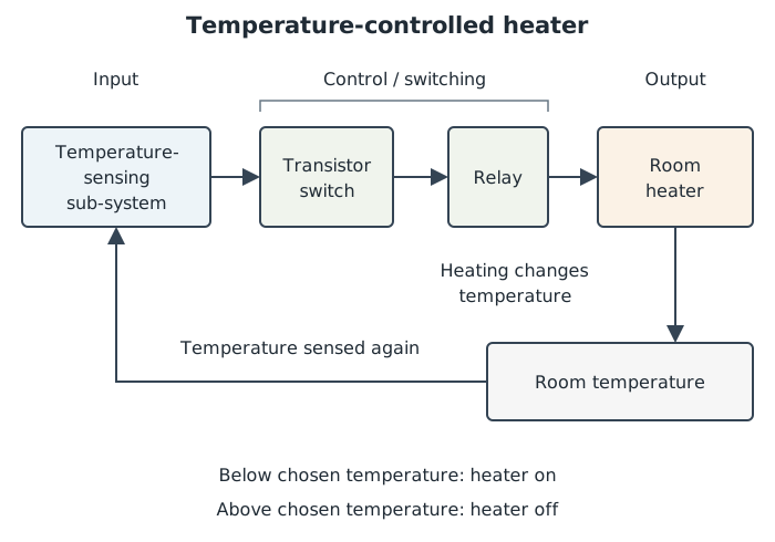
The sensor checks the temperature resulting from heating, allowing the controller to adjust the heater’s operation.
This is a closed-loop system: the controller can adjust operation using information about the result. Feedback helps maintain the required condition when circumstances change, such as when a door opens and the room cools. It can also avoid unnecessary heating once the room is warm enough.
An open-loop system does not use information about its result to correct its operation. A simple timed light sequence can run through its stages without checking what happens outside the system. This can be suitable when a fixed sequence is all that is needed, but it cannot correct an unexpected result merely by following its timer.
The feedback method must suit the condition being controlled. A heater uses temperature sensing; a light-level control system can use an LDR to monitor the resulting illumination. Feedback adds sensing and control complexity, so it is most valuable where checking and maintaining the actual result matters. A fixed decorative light sequence may not need it.
A block diagram shows what each part does and how signals move between parts. Use labelled boxes and arrows pointing in the direction of signal flow. The heater diagram separates sensing, switching and output, with a return path showing how the result is sensed again. It does not show every wire or component inside each block.
A circuit diagram shows how electrical components are connected, using standard symbols rather than pictures of their appearance. Lines represent electrical connections; a dot marks a connected junction. For example, an LED and a current-limiting resistor can be connected in series with a supply. The resistor limits the current to protect the LED. A circuit diagram communicates this connection more precisely than a box labelled ‘light output’.
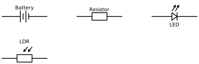
Circuit diagrams use standard symbols to identify components rather than drawings of their physical appearance.
A flowchart shows the order of actions and decisions. Start and stop use rounded terminal shapes; an input or output uses a parallelogram; a process, such as updating a count or waiting, uses a rectangle; a decision uses a diamond. Arrows show which step happens next, and decision branches are labelled Yes and No.
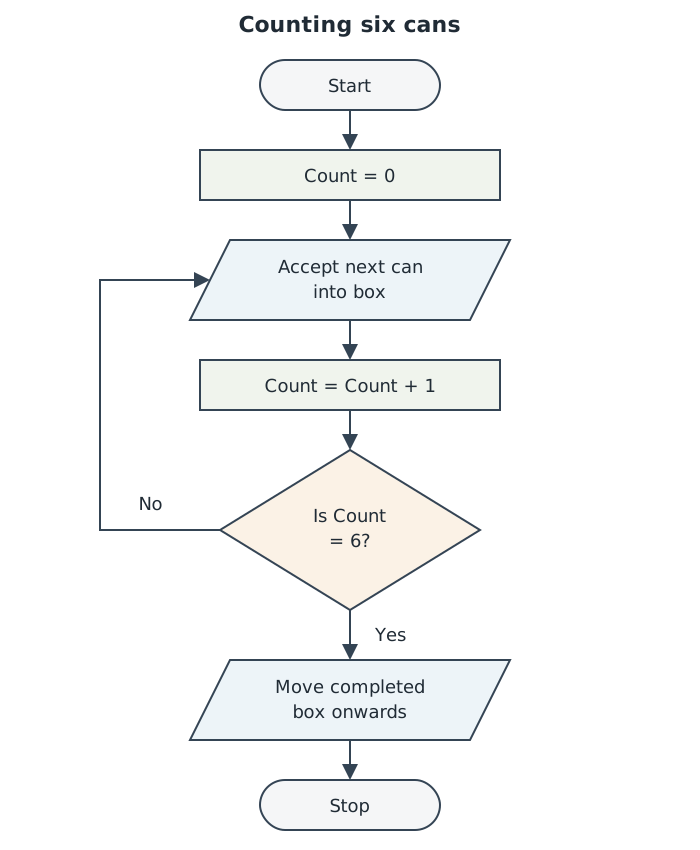
Initialise the count once, increase it for each can, and use a decision to select the next action.
To follow the counting flowchart, begin with the count at zero. Each can entering the box increases the count by one. The decision tests whether the count has reached six. The No branch returns to accept another can; the Yes branch moves the completed box onwards. The flowchart communicates the control sequence, not the physical wiring.
Together, these representations let a designer explain a product’s functions, its electrical connections and its control behaviour without confusing one kind of information with another.
Identify a component’s role in the particular system: input, processing or output. Explain what it detects, decides or does.
An LDR’s resistance falls as light increases. This does not automatically mean the sensing circuit’s output voltage falls: that depends on its arrangement.
Feedback returns information to the controller so it can adjust the output. An LED that only informs the user is not necessarily part of a feedback loop.
Use standard symbols in circuit diagrams, labelled functional boxes in block diagrams, and labelled Yes/No branches from flowchart decisions.
It can see this note and what your specification asks for.
Answers are free with an account.
1 free note left this week
Get more free notesYour answer sets when this note comes back for review, or marks it complete.
Was this note helpful?
Log in to tell us whether it helped, or to report a problem.
Last updated
Electronic system
An arrangement of connected electronic components that receives inputs, processes signals and produces outputs to perform a function.
Sensor
An input component that responds to a physical condition, such as light or temperature, by changing an electrical property or signal.
Light dependent resistor (LDR)
A resistor whose resistance decreases as the intensity of light falling on it increases.
Thermistor
A resistor whose resistance changes with temperature. In a negative temperature coefficient (NTC) thermistor, resistance decreases as temperature increases.
Analogue signal
A signal that can vary continuously over a range of values.
Digital signal
A signal represented by distinct states, commonly LOW and HIGH, or 0 and 1.
Semiconductor
A material with electrical conductivity between that of a conductor and an insulator, whose conductivity can be controlled. It is used to make components such as transistors and integrated circuits.
Integrated circuit (IC)
An electronic circuit containing many components formed together on a small semiconductor chip.
Microprocessor
An integrated circuit that executes instructions to process data and make decisions.
Feedback
Information about a system’s actual output or resulting condition that is returned to its controller to influence further operation.
Block diagram
A diagram using labelled boxes and arrows to show the functions of parts of a system and the direction of signals between them.
Circuit diagram
A diagram using standard component symbols and connections to show how an electrical circuit is arranged.
Flowchart
A diagram using standard shapes and arrows to show the sequence of operations and decisions in a control process.
Put your knowledge into practice — try past paper questions for Design and Technology
Electronic system
An arrangement of connected electronic components that receives inputs, processes signals and produces outputs to perform a function.
Sensor
An input component that responds to a physical condition, such as light or temperature, by changing an electrical property or signal.
Light dependent resistor (LDR)
A resistor whose resistance decreases as the intensity of light falling on it increases.
Thermistor
A resistor whose resistance changes with temperature. In a negative temperature coefficient (NTC) thermistor, resistance decreases as temperature increases.
Analogue signal
A signal that can vary continuously over a range of values.
Digital signal
A signal represented by distinct states, commonly LOW and HIGH, or 0 and 1.
Semiconductor
A material with electrical conductivity between that of a conductor and an insulator, whose conductivity can be controlled. It is used to make components such as transistors and integrated circuits.
Integrated circuit (IC)
An electronic circuit containing many components formed together on a small semiconductor chip.
Microprocessor
An integrated circuit that executes instructions to process data and make decisions.
Feedback
Information about a system’s actual output or resulting condition that is returned to its controller to influence further operation.
Block diagram
A diagram using labelled boxes and arrows to show the functions of parts of a system and the direction of signals between them.
Circuit diagram
A diagram using standard component symbols and connections to show how an electrical circuit is arranged.
Flowchart
A diagram using standard shapes and arrows to show the sequence of operations and decisions in a control process.