Loading…


Loading…
Loading…
Loading…
Edexcel GCSE Combined Science · 1SC0
Edexcel 1SC0 · Current, voltage, and resistance Check the specification (PDF) (opens in a new tab)
To understand current in a metal wire, start with the particles that make up atoms. An atom has a central nucleus, containing protons and neutrons, with electrons around it.
| Particle | Position in the atom | Relative mass | Relative charge |
|---|---|---|---|
| Proton | In the nucleus | 1 | +1 |
| Neutron | In the nucleus | 1 | 0 |
| Electron | Around the nucleus | About 0.0005 | −1 |
These masses and charges are relative values, not masses in kilograms or charges in coulombs. A proton and a neutron have approximately the same mass; an electron has a much smaller mass. Almost all the atom’s mass is therefore concentrated in its nucleus. Protons make the nucleus positively charged, while electrons carry negative charge.
Electric current is the rate of flow of charge: the amount of charge passing a point in a circuit each second. Charge is measured in coulombs (C) and current in amperes (A), often called amps.
A current of 1 A means that 1 C of charge passes a point every second. A larger current means more charge passes each second, not simply that more charge is present in the wire.
In metals, some electrons can move through the material. Current in a metal is a flow of electrons; the protons and neutrons in the nuclei do not travel around the circuit.
For a steady current, the charge transferred is:
Here, is charge in coulombs, is current in amperes and is time in seconds. The same relationship can be rearranged to give or .
For instance, if 4 C passes a point in 500 s, the current is , or 8 mA. Using the charge equation in reverse, . This is the total charge that passes that point during the time interval.
A working circuit needs a source of potential difference, such as a cell or battery, and a closed conducting path. The source provides the electrical driving effect that makes charge flow through the circuit.
Closing a switch completes the path. Opening it makes a gap, so current cannot flow around that path. In a simple lamp circuit, the lamp lights when the switch is closed and goes out when it is opened.
Circuit diagrams use conventional current, directed from the positive terminal to the negative terminal through the external circuit. Because electrons are negatively charged, their flow in metal wires is in the opposite direction: from negative to positive.
A circuit diagram shows electrical connections, not the physical positions or appearance of the equipment. Wires are drawn as lines, and each component has a standard symbol. You can move a symbol on the page without changing the circuit, provided its connections remain the same.
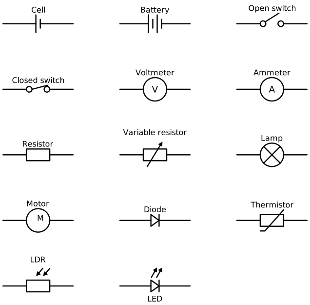
Standard symbols represent components and their electrical connections, rather than their physical appearance.
The symbols can be recognised by their distinctive features:
| Component | How to recognise its symbol and what it represents |
|---|---|
| Cell | One long line and one short line. The long line is positive (+); the short line is negative (−). |
| Battery | Several long–short line pairs, representing cells connected together. |
| Switch | A break with a movable contact. The contact either bridges the gap (closed) or leaves it open. |
| Ammeter | A circle containing A; measures current. |
| Voltmeter | A circle containing V; measures potential difference. |
| Resistor | A rectangle; limits current. |
| Variable resistor | A rectangle crossed by a diagonal arrow; its resistance can be adjusted. |
| Lamp | A circle containing a cross; transfers electrical energy to light and heating. |
| Motor | A circle containing M; produces movement. |
| Diode | A triangle pointing towards a bar; allows current in one direction only. Conventional current can pass towards the bar, not the other way. |
| Thermistor | A resistor symbol crossed by a diagonal line with a short bent end; its resistance depends on temperature. |
| LDR | A resistor inside a circle with arrows pointing towards it; its resistance depends on light intensity. |
| LED | A diode symbol with arrows pointing away from it; emits light when current passes in the permitted direction. |
To draw a simple switched lamp circuit, place a cell, switch and lamp along one loop, then join their terminals with wires. Make the switch closed if the diagram is intended to show current flowing. Trace the path from the cell’s positive terminal through the components and back to its negative terminal to check that the loop is complete.
A dot where wires meet marks an electrical junction. When reading a diagram, follow the actual connections rather than judging whether components look close together.
In a series circuit, components are connected end to end. There is only one path, so the charge passing through one component must also pass through the others.
The current is the same at every point in the loop. If an ammeter reads 0.5 A before the first lamp, the current between the lamps and after the second lamp is also 0.5 A. The lamps transfer energy; they do not use up current.
A break anywhere in this single path stops current throughout the circuit. A switch in the loop therefore controls all the series components together. The supply’s potential difference is shared between the components.
In a parallel circuit, components are connected in separate branches between the same two junctions. Charge has more than one possible route through the circuit.
Current splits at the first junction and recombines where the branches join. The potential difference is the same across each branch connected across the supply. The branch currents need not be equal.
Opening a switch in one branch stops current in that branch but leaves the other complete branches working. A switch in the shared part of the circuit can still turn all branches off.
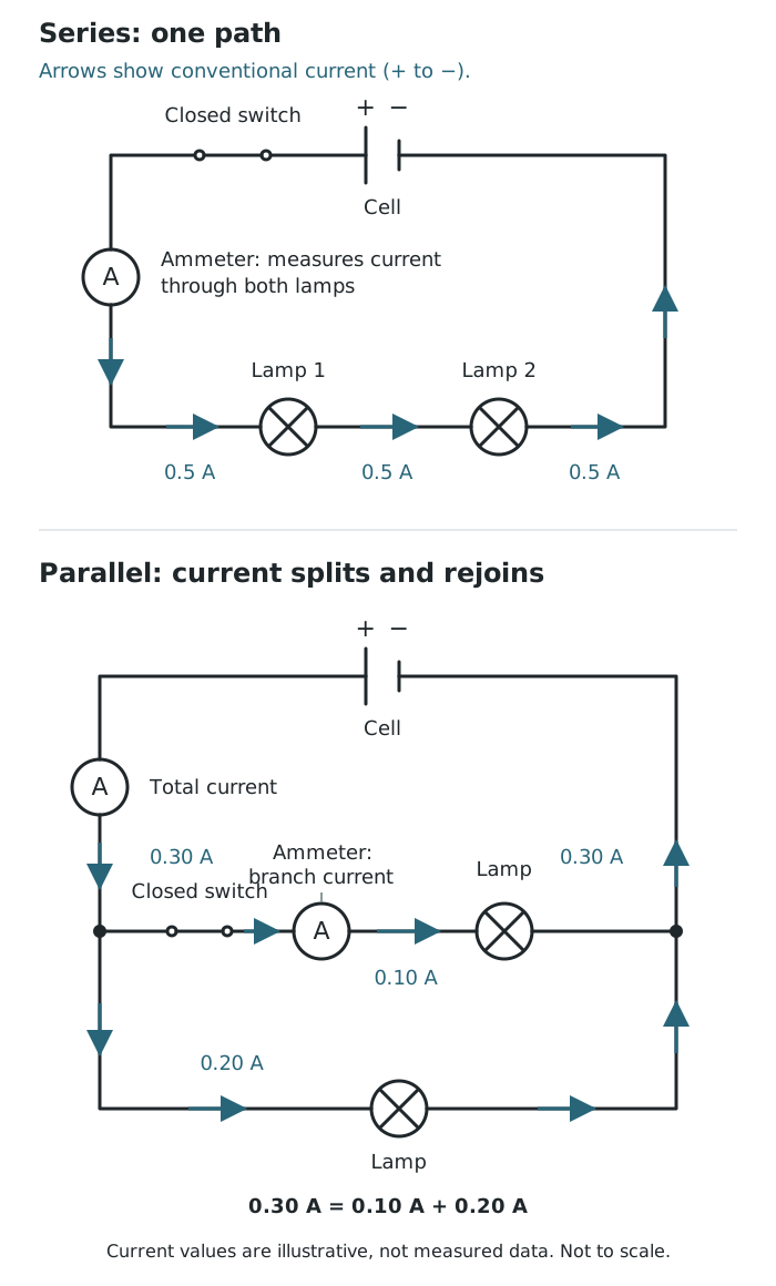
Currents show the same current throughout a series loop and conservation of current where parallel branches split and rejoin.
An ammeter must be connected in series with the component whose current you want to measure. This means inserting it into the same path so the current through the component also passes through the meter.
For a series circuit, an ammeter anywhere in the loop measures the current through every component. In a parallel circuit, its position matters: an ammeter in one branch measures that branch’s current, whereas an ammeter in the shared wire next to the supply measures the total current.
Charge does not disappear or build up at a junction during steady operation. The rate at which charge arrives must equal the total rate at which it leaves. Therefore:
For two outgoing branches, this can be written as .
In the illustrated parallel circuit, 0.30 A reaches the junction. One branch carries 0.10 A and the other carries 0.20 A, so . Where the branches rejoin, their currents add back to 0.30 A. The total is conserved even though the split is unequal.
Get unlimited access to all revision notes, key terms, and exam tips.
Current is charge flow per second. In metals, the moving charges are electrons.
Use standard circuit symbols and straight lines for wires. The long line of a cell is the positive terminal; the short line is the negative terminal.
To measure a component’s current, put the ammeter in the same path as that component, not in a separate parallel branch.
Use seconds and amperes in Q = It. Convert minutes to seconds and milliamperes to amperes: 1 mA = 0.001 A.
Current is not used up by a lamp. At a junction, add the branch currents; do not assume they are equal.
Conventional current and electron flow have opposite directions.
Proton
A particle in an atom’s nucleus with relative mass 1 and relative charge +1.
Neutron
A particle in an atom’s nucleus with relative mass 1 and no electric charge.
Electron
A negatively charged particle found around an atom’s nucleus, with relative charge −1 and a very small relative mass of about 0.0005.
Electric current
The rate of flow of electric charge, measured in amperes (A). A current of 1 A means 1 C of charge passes a point each second.
Electric charge
An electrical property carried by particles such as protons and electrons. The amount of charge transferred is measured in coulombs (C).
Ammeter
A meter connected in series with a component to measure the current through it.
Series circuit
A circuit arrangement in which components are connected end to end along a single path.
Parallel circuit
A circuit arrangement with separate branches, providing more than one path for current.
Junction
A point in a circuit where current can split between paths or where paths join together.
Conservation of current
The rule that the total current entering a circuit junction equals the total current leaving it.
Conventional current
The direction assigned to current: from the positive terminal to the negative terminal through the external circuit. Electron flow in metal wires is in the opposite direction.
Put your knowledge into practice — try past paper questions for Combined Science
Proton
A particle in an atom’s nucleus with relative mass 1 and relative charge +1.
Neutron
A particle in an atom’s nucleus with relative mass 1 and no electric charge.
Electron
A negatively charged particle found around an atom’s nucleus, with relative charge −1 and a very small relative mass of about 0.0005.
Electric current
The rate of flow of electric charge, measured in amperes (A). A current of 1 A means 1 C of charge passes a point each second.
Electric charge
An electrical property carried by particles such as protons and electrons. The amount of charge transferred is measured in coulombs (C).
Ammeter
A meter connected in series with a component to measure the current through it.
Series circuit
A circuit arrangement in which components are connected end to end along a single path.
Parallel circuit
A circuit arrangement with separate branches, providing more than one path for current.
Junction
A point in a circuit where current can split between paths or where paths join together.
Conservation of current
The rule that the total current entering a circuit junction equals the total current leaving it.
Conventional current
The direction assigned to current: from the positive terminal to the negative terminal through the external circuit. Electron flow in metal wires is in the opposite direction.
Units: in C, in A, in s. .
| Series | Parallel |
|---|---|
| One path | Separate branches |
| Same current everywhere | Total current splits between branches |
| Supply potential difference is shared | Same potential difference across branches |
| A break stops the whole loop | A break in one branch leaves other complete branches working |
Add all incoming currents and all outgoing currents. Branch currents need not be equal.
Get unlimited access to all revision notes, key terms, and exam tips.