

Loading…
Loading…
Loading…
AQA GCSE Combined Science: Synergy · 8465
AQA 8465 · 4.7.2.3 Series and Parallel Circuits Check the specification (PDF) (opens in a new tab)
Required Practical 16 investigates how resistance depends on the length of a wire at constant temperature and on the arrangement of resistors in series and parallel.
Resistance describes how strongly a component opposes current. To find it experimentally, measure the current through the component with an ammeter in series, and the potential difference across it with a voltmeter in parallel. The ammeter lies in the current’s path; the voltmeter connects to the two ends of the component being tested.
Use:
Here, is resistance in ohms (), is potential difference in volts (V), and is current in amperes (A). For example, a potential difference of 1.5 V and a current of 0.30 A give a resistance of .
You need a low-voltage power supply, connecting leads, a switch, an ammeter, a voltmeter, thin uninsulated resistance wire, two crocodile clips, a metre ruler and tape.
Tape the wire straight along the ruler. Fix one crocodile clip at the zero mark and place the other at 10 cm. The distance between the clips is the length being tested: the unused wire beyond the clips is not part of that measurement.
Connect the supply, switch, ammeter and tested wire section in series. Connect the voltmeter across that same section, between the clips. With the switch open, check the connections against the circuit diagram and check that the meters read zero.
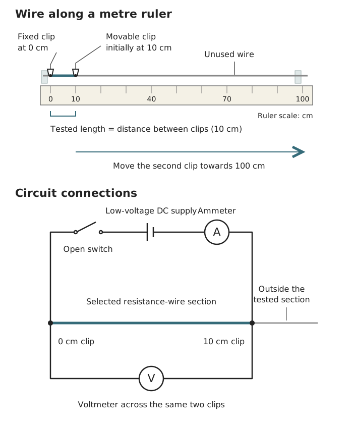
The ammeter measures current through the selected wire section; the voltmeter measures potential difference between its two clips.
The independent variable is the length of wire between the clips. The dependent variable is its calculated resistance. Use the same wire throughout so that its material and diameter remain constant. Keep the supply setting constant and, crucially, keep the wire’s temperature as constant as possible.
Use a low supply potential difference, such as 1.5 V, to keep the current small. Close the switch briefly and record the current and potential difference once the meter readings are steady. Open the switch immediately afterwards.
Move the second clip to 20 cm, then 30 cm, continuing in 10 cm intervals up to 100 cm. For each length, measure both current and potential difference again. Do not assume that the potential difference across the wire is unchanged just because the supply setting is unchanged.
Current heats the wire, and a hotter metal wire has a higher resistance. If temperature changes, the results no longer show the effect of length alone. Switch off between readings and allow the wire to cool before taking another reading. Repeat measurements at each length and calculate a mean resistance to reduce the influence of random variation.
Safety: the uninsulated wire can become hot. Do not touch it while the circuit is on, and let it cool before handling it. Switch off before moving clips or changing connections. If there is a burning smell, switch off immediately and tell the teacher. Keep liquids away from the electrical equipment.
Record results in a table with columns for length of wire (cm), current (A), potential difference (V) and resistance (). Calculate each resistance using .
Plot resistance on the vertical axis and wire length on the horizontal axis. If using metres, convert the lengths first: 10 cm is 0.10 m. Draw a line of best fit rather than joining each point separately.
For a uniform wire at constant temperature, the expected relationship is a straight line through the origin: resistance is directly proportional to length. Doubling the tested length doubles its resistance. A longer wire provides a longer path through the material, increasing the opposition to current.
Real readings may scatter around the expected line. Check unusual points by repeating the measurement, checking the clip positions and contacts, and ensuring that the wire has cooled. Measure between the actual contact points of the clips, rather than assuming that their positions are exact.
For the second investigation, use two resistors, the low-voltage supply, switch, leads and meters. Measure each resistor separately first, with the ammeter in series and the voltmeter across the resistor. Record and and calculate each individual resistance.
Then connect the same two resistors in series. Place the voltmeter across both resistors together, and keep the ammeter in series with the combination. Close the switch briefly, record steady readings and open it again.
With the supply switched off, rearrange the resistors in parallel. The ammeter must be in the main circuit before the current splits or after it rejoins, so that it measures total current, not one branch current. Connect the voltmeter across the whole parallel combination.
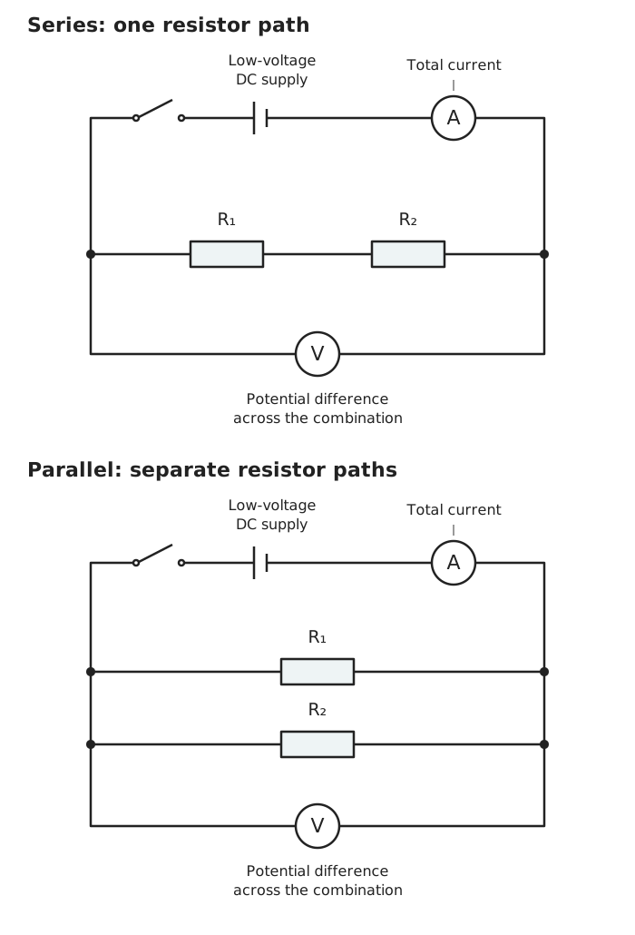
For both arrangements, total resistance is found from the potential difference across the combination divided by the total current.
Keep the same resistors and supply setting for the comparison, and minimise heating by switching off between readings. Here, the factor changed is the arrangement of the resistors; the dependent variable is their total resistance. Repeat the readings for each arrangement.
For each arrangement, calculate total resistance from the measured potential difference across the combination divided by the total current through it.
In series, the measured total resistance should be approximately the sum of the individual resistances:
There is only one path, so current must pass through both resistors.
In parallel, the measured total resistance should be less than the resistance of either individual resistor. The extra path allows a greater total current for the same potential difference. You can test this conclusion using the meter readings without using a formula for combining parallel resistor values.
The investigation is complete when you have repeated measurements for the wire lengths and for the resistor arrangements, calculated their resistances, and used those results to identify the relationships.
in , in V, in A.
The tested wire length is the distance between the crocodile clips, not the full length of wire on the ruler.
Explain temperature control: heating changes resistance, so use a small current, switch off between readings and allow the wire to cool.
To measure total resistance, use the total current and the potential difference across the whole resistor combination.
A rising straight line shows direct proportionality only if it passes through the origin.
You may determine a parallel combination’s resistance from measured V and I. Calculating it from the individual resistor values using a parallel-resistance formula is not required.
It can see this note and what your specification asks for.
Answers are free with an account.
1 free note left this week
Get more free notesYour answer sets when this note comes back for review, or marks it complete.
Was this note helpful?
Log in to tell us whether it helped, or to report a problem.
Last updated
Resistance
A measure of how strongly a component opposes electric current, calculated using and measured in ohms ().
Potential difference
The energy transferred per unit charge between two points in a circuit, measured in volts (V).
Current
The rate of flow of electric charge, measured in amperes (A).
Independent variable
The factor deliberately changed in an investigation.
Dependent variable
The factor measured or calculated to find the effect of changing the independent variable.
Control variable
A factor kept constant so that it does not affect the comparison being made.
Direct proportionality
A relationship in which one quantity is a constant multiple of another; its graph is a straight line through the origin.
Put your knowledge into practice — try past paper questions for Combined Science: Synergy
Resistance
A measure of how strongly a component opposes electric current, calculated using and measured in ohms ().
Potential difference
The energy transferred per unit charge between two points in a circuit, measured in volts (V).
Current
The rate of flow of electric charge, measured in amperes (A).
Independent variable
The factor deliberately changed in an investigation.
Dependent variable
The factor measured or calculated to find the effect of changing the independent variable.
Control variable
A factor kept constant so that it does not affect the comparison being made.
Direct proportionality
A relationship in which one quantity is a constant multiple of another; its graph is a straight line through the origin.
Measure each resistor alone, then the same pair in series and in parallel. Keep the supply setting unchanged and minimise heating.
Use potential difference across the whole combination and total current to calculate total resistance.