

Loading…
Loading…
Loading…
AQA GCSE Combined Science: Synergy · 8465
AQA 8465 · 4.7.2.4 Check the specification (PDF) (opens in a new tab)
A uses standard symbols to show electrical components and how they are connected. It is not a picture of the apparatus on a bench: the shape or length of a drawn wire does not show the actual wire’s shape or length. What matters is which components are connected to one another.
In a series circuit, the components are connected along one loop, with no branches. A cell or battery supplies a potential difference, and the loop must be complete for current to flow. An open switch breaks the loop; closing it joins the contacts and completes the path.
Each component has its own symbol. Using the same symbols makes a circuit understandable even when the real components look different.
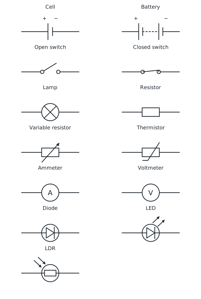
Standard circuit symbols: inward arrows identify an LDR, outward arrows identify an LED, and the thermistor’s sloping line has no arrowhead.
A cell is represented by one long line and one short line. A battery has repeated pairs of these lines. A lamp has a cross inside a circle, while a resistor is shown as a rectangle. A variable resistor has an arrow through the resistor symbol, showing that its resistance can be adjusted.
An ammeter has an A inside a circle and measures current. A voltmeter has a V inside a circle and measures potential difference across a component. The open and closed switch symbols show whether the contacts are separated or joined.
Some symbols include details that distinguish related components. A light-dependent resistor (LDR) is drawn as a resistor inside a circle, with two arrows pointing towards it to represent incoming light. Its resistance depends on the light falling on it. A thermistor is a component whose resistance depends on temperature. Its symbol is a resistor crossed by a sloping line that bends into a short horizontal tail at one end; unlike the variable resistor’s line, it has no arrowhead. Both components can act as sensors.
A diode allows current in only one direction. Its symbol has a triangle-shaped part pointing towards a bar, inside a circle. A light-emitting diode (LED) uses the diode symbol with two arrows pointing outwards, representing emitted light. These outward arrows contrast with the inward arrows on an LDR.
On a cell symbol, the long line is the positive terminal and the short line is the negative terminal. The same convention identifies the outer terminals of a battery. The symbols can be rotated, so positive does not always mean the left-hand side or the top of the diagram.
Conventional current flows through the external circuit from the positive terminal towards the negative terminal. To follow its direction, start at the long line of the cell and trace the connected wires and components back to the short line.
For a diode, conventional current can pass through it towards the bar, but not in the reverse direction. A complete loop alone therefore does not guarantee current: a diode connected the wrong way round can prevent it.
Suppose a circuit contains a cell, a closed switch, a lamp and an ammeter, with a voltmeter measuring the potential difference across the lamp.
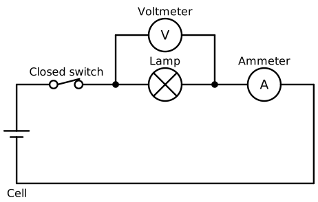
The ammeter lies along the main series path; the voltmeter connects across the lamp.
The ammeter is in series: it lies along the same path as the lamp, so the lamp’s current passes through it. The voltmeter is connected in parallel across the lamp: its two connections go to opposite sides of the lamp. It is a measuring branch, not another component placed along the main series path.
To draw a circuit, work systematically around its connections. Draw the cell symbol, then add each component’s symbol in sequence, joining them with straight wires. Complete the return connection to the other terminal. Add a voltmeter, if needed, across the component being measured.
To interpret a diagram, use the reverse process: identify the symbols, locate the supply’s terminals, then trace the path. Check for open switches or gaps and inspect any diode’s orientation. Moving a symbol to another side of the drawing does not change the circuit if its connections remain the same.
Use a ruler for wires and draw symbols clearly, with no unintended gaps between wires and components.
Check the long and short lines of each cell before adding positive and negative labels or current arrows.
When deciding whether current can flow, check both that the circuit is complete and that any diode faces the conducting direction.
Practise drawing symbols from their names as well as recognising them.
It can see this note and what your specification asks for.
Answers are free with an account.
1 free note left this week
Get more free notesYour answer sets when this note comes back for review, or marks it complete.
Was this note helpful?
Log in to tell us whether it helped, or to report a problem.
Last updated
Circuit diagram
A representation of an electrical circuit using standard symbols to show components and their connections.
Series circuit
An electrical circuit in which the components are connected along a single loop, with no branches.
Conventional current
The agreed direction of current through an external circuit: from the positive terminal of the supply towards its negative terminal.
Diode
An electrical component that allows current to flow in one direction but not the opposite direction.
LDR
A light-dependent resistor: an electrical component whose resistance depends on the light falling on it.
Thermistor
An electrical component whose resistance depends on its temperature.
Put your knowledge into practice — try past paper questions for Combined Science: Synergy
Circuit diagram
A representation of an electrical circuit using standard symbols to show components and their connections.
Series circuit
An electrical circuit in which the components are connected along a single loop, with no branches.
Conventional current
The agreed direction of current through an external circuit: from the positive terminal of the supply towards its negative terminal.
Diode
An electrical component that allows current to flow in one direction but not the opposite direction.
LDR
A light-dependent resistor: an electrical component whose resistance depends on the light falling on it.
Thermistor
An electrical component whose resistance depends on its temperature.