

Loading…
Loading…
Loading…
OCR GCSE Combined Science B · J260
OCR J260 · Circuit Properties and Problem Solving Check the specification (PDF) (opens in a new tab)
An electric circuit needs a complete conducting path for a sustained current to flow. Current is the rate of flow of charge. A cell or battery transfers energy electrically, and components such as bulbs transfer that energy to the surroundings as light and heating.
Charge is not consumed by a bulb. This distinction helps explain circuits: current describes charge flow, whereas potential difference describes energy transferred per unit charge.
The potential difference between two points is the work done on, or by, each unit of charge as it moves between those points. Work done means energy transferred:
Here is potential difference in volts (V), is work done or energy transferred in joules (J), and is charge in coulombs (C). One volt means one joule transferred per coulomb.
For example, suppose 12 J is transferred as 3 C of charge passes through a component. Its potential difference is . Each coulomb transfers 4 J, rather than the component receiving only 4 J altogether.
Rearranging gives and . A battery does work on charge; components transfer energy from the electrical system to other stores or to the surroundings.
In a series circuit, components are connected end to end along one path. Charge passing through one component must also pass through the others, so the current is the same throughout:
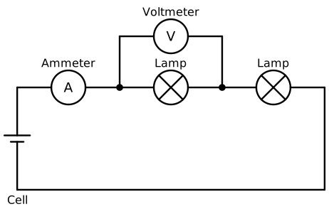
Two bulbs share one path. The ammeter measures the common current, and the voltmeter measures the potential difference across one bulb.
The battery's energy transfer per coulomb equals the total energy transferred per coulomb in the components. Consequently, their potential differences add to the supply potential difference:
Identical bulbs share the supply potential difference equally. Different components do not necessarily share it equally. If the path is broken anywhere, current stops throughout the circuit.
Resistance is opposition to current. Adding a resistor in series increases the equivalent resistance because every charge must pass through this additional opposition. For series resistors:
For a fixed supply potential difference, increasing one resistor's resistance increases the and reduces the through component.
The potential differences also change. Across a resistor, . In a series circuit containing other unchanged resistors, the increased resistor takes a larger share of the supply potential difference. The unchanged resistors take smaller shares because their current has fallen. The shares still add to the supply potential difference.
For example, suppose two fixed resistors of each are connected in series across 6 V. Their equivalent resistance is , so the current is 1 A and each has 3 V across it. Replacing one with a resistor gives a total of and a current of 0.5 A. The unchanged resistor now has 1.5 V across it, while the replacement has 4.5 V.
In a parallel circuit, charge divides between branches. Each charge passes through one branch rather than through every branch. The branch currents add to the total current:
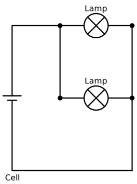
Each bulb has its own branch connected across the cell, so each receives the same supply potential difference.
Each branch connects between the same two junctions, so each has the same potential difference. For branches connected directly across the supply:
Equal potential differences do not guarantee equal currents: a higher-resistance branch carries less current. If one branch is disconnected, the others still provide complete paths.
Adding a resistor as another parallel branch decreases the equivalent resistance. It provides an extra route for charge, allowing a greater total current at the same supply potential difference. No calculation of parallel equivalent resistance is needed to explain this.
At a fixed supply potential difference, increasing the resistance of one branch reduces its current. The potential difference across it stays the same, and the currents in unchanged branches stay the same. The total supply current therefore decreases.
Use a low-voltage cell or regulated d.c. supply, three identical bulbs with holders, connecting leads and an ammeter. A voltmeter can also measure the potential difference across each bulb. The diagrams show the two-bulb arrangements; begin with one bulb and then compare arrangements with two and three.
Keep the supply potential difference, bulb type and viewing conditions the same. Use a supply setting suitable for the bulbs. Switch off before changing connections, never connect a wire directly across the supply, and allow hot bulbs to cool before handling them.
For the series investigation, connect one bulb and record its brightness and the current. Switch off, add a second bulb in series, then switch on again. Wait until the glow and meter readings are steady before recording them. Repeat with three bulbs. An ammeter goes in series; moving it to another position in the same loop demonstrates that the current is unchanged around the loop.
More bulbs in series increase the circuit's resistance and reduce its current. Identical bulbs glow equally brightly within each arrangement, but become dimmer as more are added. Each also receives a smaller share of the supply potential difference.
For the parallel investigation, begin with one bulb across the supply. Add a second and then a third bulb on separate branches, switching off to rewire each time. Record steady brightness observations and the total current, measured with the ammeter in the supply lead before the current divides.
With the supply potential difference maintained, adding parallel bulbs leaves the brightness of existing bulbs approximately unchanged. Each bulb still has the full supply potential difference, but the total current increases. Repeating the comparisons checks that the pattern is consistent. Brightness is a qualitative observation, not a precise measurement of current.
To measure potential difference, connect a voltmeter in parallel across a bulb. This checks the shared potential differences in series and the equal potential differences across parallel branches.
Replace the series resistors mentally with one equivalent resistor, calculate the common current, then return to the individual resistors.
Suppose , and fixed resistors are connected in series across a 12 V supply. Their equivalent resistance is . Using , the circuit current is .
That 1 A passes through all three resistors. Applying gives potential differences of 2 V, 4 V and 6 V respectively. Their sum is 12 V, matching the supply and checking the energy-transfer rule. The largest resistance takes the largest potential difference because the current is common to all three.
: volts; : joules; : coulombs. is energy transferred per unit .
Identify connections, not the shape of the drawing: series components share one path; parallel branches connect between the same two junctions.
Current is not used up by a bulb. Energy is transferred, while charge continues around the circuit.
When using V = IR, use the current through and potential difference across the same resistor.
For series calculations, find the equivalent resistance first, then the circuit current, then individual potential differences.
Explain resistance changes at a fixed supply potential difference. Parallel branches have equal potential differences, but their currents need not be equal.
It can see this note and what your specification asks for.
Answers are free with an account.
1 free note left this week
Get more free notesYour answer sets when this note comes back for review, or marks it complete.
Was this note helpful?
Log in to tell us whether it helped, or to report a problem.
Last updated
Charge
An electrical property of particles. Moving charge forms an electric current; charge is measured in coulombs (C).
Current
The rate of flow of electric charge, measured in amperes (A).
Potential difference
The work done, or energy transferred, per unit charge between two points: . It is measured in volts (V), where one volt is one joule per coulomb.
Resistance
Opposition to electric current, measured in ohms (). Resistance relates potential difference and current through .
Series circuit
A circuit in which components are connected along one path, so the same current passes through each component.
Parallel circuit
A circuit containing separate branches connected between the same two junctions, providing more than one path for charge.
Equivalent resistance
The resistance of a single resistor that could replace a combination of resistors while producing the same total current at the same supply potential difference.
Put your knowledge into practice — try past paper questions for Combined Science B
Charge
An electrical property of particles. Moving charge forms an electric current; charge is measured in coulombs (C).
Current
The rate of flow of electric charge, measured in amperes (A).
Potential difference
The work done, or energy transferred, per unit charge between two points: . It is measured in volts (V), where one volt is one joule per coulomb.
Resistance
Opposition to electric current, measured in ohms (). Resistance relates potential difference and current through .
Series circuit
A circuit in which components are connected along one path, so the same current passes through each component.
Parallel circuit
A circuit containing separate branches connected between the same two junctions, providing more than one path for charge.
Equivalent resistance
The resistance of a single resistor that could replace a combination of resistors while producing the same total current at the same supply potential difference.
Compare one, two and three identical bulbs at the same supply potential difference. Record steady brightness and current; switch off before rewiring. Ammeter: in series. Voltmeter: across a component.
For series resistors: add resistances → use → use for each resistor → check that the potential differences add to the supply.