

Loading…
Loading…
Loading…
OCR GCSE Combined Science B · J260
OCR J260 · Circuit Properties and Problem Solving Check the specification (PDF) (opens in a new tab)
To investigate a component, we need to measure the current through it and the potential difference across it. Current is the rate of flow of charge; potential difference describes the energy transferred per unit charge. Together, these readings allow us to calculate resistance:
Here, is resistance in ohms (), is potential difference in volts (V), and is current in amperes (A).
A low-voltage direct current supply drives charge around the test circuit in one direction. The test component, variable resistor and ammeter are connected in series. Because the same current passes through these components, the ammeter measures the current through the test component. The voltmeter connects in parallel across only the test component, measuring the potential difference between its two ends.
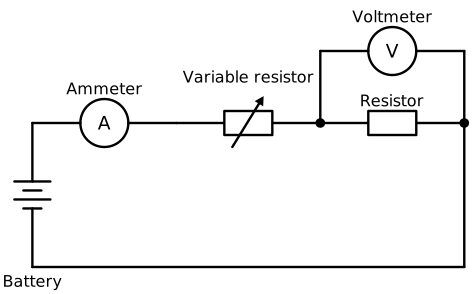
The ammeter measures current through the test resistor. The voltmeter measures potential difference across it. Replace the test resistor with the component under investigation.
Increasing the variable resistor’s resistance reduces the current. Adjusting it gives a range of current and potential difference readings without rebuilding the circuit. An adjustable d.c. supply can also be used to change the readings.
An I–V characteristic shows how current changes with potential difference. Use a low-voltage d.c. supply, connecting leads, an ammeter, a voltmeter, a variable resistor and the component being tested.
For a suitable fixed resistor, a school investigation might use supply settings from 0 to 6 V. The safe range depends on the component: do not assume that every component, especially a diode, can withstand the same settings. Keep current within the component’s rating, use the variable resistor to limit it, and avoid short circuits. Filament lamps and heated components can become hot; let them cool before touching them.
You have enough readings when they cover the chosen safe range and show the relationship clearly. Calculate at non-zero readings to see whether resistance stays constant or changes. A fixed resistor kept at constant temperature provides a useful comparison: its I–V graph is a straight line through the origin.
A filament lamp contains a thin wire that becomes hot enough to glow when current flows through it. As current increases, the filament gets hotter and the lamp becomes brighter. The higher temperature increases the filament’s resistance.
Consequently, doubling the potential difference does not double the current. On an I–V graph, the curve becomes less steep at larger potential differences: current still increases, but by progressively smaller amounts for equal increases in potential difference. Reversing the supply gives a corresponding curve on the negative side because the filament heats whichever way the current flows.
A diode behaves differently in its two directions. In the forward direction, little current flows at small potential differences; once the potential difference is sufficient, current rises rapidly. In the reverse direction, its resistance is very high and current is negligible within the safe testing range.
Reversing the supply therefore reveals a strongly asymmetric I–V characteristic. Unlike a filament lamp, a diode does not produce matching positive and negative curves. Limit the current carefully when testing the forward direction, where a small increase in potential difference can cause a large increase in current.
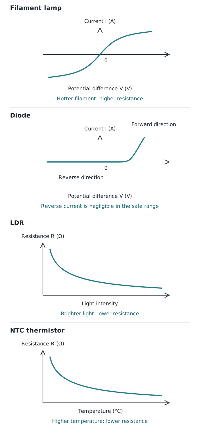
Filament lamps and diodes have different I–V characteristics. For an LDR and an NTC thermistor, resistance depends on the surrounding conditions.
An LDR’s resistance is high in dim light and lower in bright light. To investigate this, replace the test component with an LDR and illuminate it using a lamp whose brightness can be adjusted.
Begin with the lamp off in a darkened setting. Record current and potential difference, then increase the illumination in stages. Keep the lamp’s position fixed, keep other lighting unchanged, and avoid warming the LDR. Place the lamp close enough to illuminate it, but not touching it. After each change, wait for the readings to settle and calculate the LDR’s resistance.
The calculated resistance should decrease as illumination increases. At the same potential difference across the LDR, a lower resistance means a larger current. This response makes LDRs useful for sensing light levels, such as in automatic outdoor lighting.
When investigating the effect of changing current through an LDR instead, keep its illumination and temperature constant. Otherwise, a resistance change caused by brighter light could be mistaken for an effect of changing current.
An NTC thermistor has a high resistance when cold and a lower resistance when hot. To investigate temperature, use it as the test component and place a controlled heater nearby, without touching it. Use a thermometer to record the temperature near the thermistor.
Start with the heater off. Increase the heating in stages, allowing the temperature and meter readings to settle before recording temperature, current and potential difference. Calculate resistance for each temperature, then compare the results or plot resistance against temperature. Keep the electrical testing current small so that the thermistor is not significantly warmed by the measurement itself.
As temperature rises, the calculated resistance decreases. At the same potential difference across the thermistor, current therefore increases. This makes thermistors useful as temperature sensors, including in electronic thermostats. Handle the heater carefully, keep leads away from hot surfaces and allow the apparatus to cool afterwards.
Increasing current through a thermistor can itself cause heating. If this raises its temperature, its resistance falls. To distinguish an effect of current from an effect of temperature, monitor or control its temperature. The key contrast is that heating increases a filament’s resistance but decreases an NTC thermistor’s resistance.
Draw the ammeter in series and the voltmeter in parallel across the component being tested, not across the whole circuit.
For an I–V graph, put potential difference on the horizontal axis and current on the vertical axis. Label both axes with units.
Calculate resistance using the potential difference across the test component, not necessarily the supply voltage.
State what is kept constant: temperature when testing an LDR, and light intensity when investigating how its current changes.
An NTC thermistor’s resistance decreases as temperature increases; a filament lamp’s resistance increases as its filament gets hotter.
Use a smooth best-fit curve for a curved relationship rather than joining every reading with straight lines.
It can see this note and what your specification asks for.
Answers are free with an account.
1 free note left this week
Get more free notesYour answer sets when this note comes back for review, or marks it complete.
Was this note helpful?
Log in to tell us whether it helped, or to report a problem.
Last updated
Direct current
An electric current that flows in one direction.
Ammeter
A meter connected in series to measure current in amperes (A).
Voltmeter
A meter connected in parallel across a component to measure potential difference in volts (V).
Resistance
A measure of how strongly a component opposes current, calculated using and measured in ohms ().
I–V characteristic
A graph showing how the current through a component varies with the potential difference across it.
Variable resistor
A component whose resistance can be adjusted to change the current in a circuit.
Diode
A component that allows substantial current in one direction but has very high resistance in the reverse direction.
NTC thermistor
A temperature-sensitive resistor whose resistance decreases as its temperature increases. NTC means negative temperature coefficient.
LDR
A light-dependent resistor whose resistance decreases as the light intensity falling on it increases.
Put your knowledge into practice — try past paper questions for Combined Science B
Direct current
An electric current that flows in one direction.
Ammeter
A meter connected in series to measure current in amperes (A).
Voltmeter
A meter connected in parallel across a component to measure potential difference in volts (V).
Resistance
A measure of how strongly a component opposes current, calculated using and measured in ohms ().
I–V characteristic
A graph showing how the current through a component varies with the potential difference across it.
Variable resistor
A component whose resistance can be adjusted to change the current in a circuit.
Diode
A component that allows substantial current in one direction but has very high resistance in the reverse direction.
NTC thermistor
A temperature-sensitive resistor whose resistance decreases as its temperature increases. NTC means negative temperature coefficient.
LDR
A light-dependent resistor whose resistance decreases as the light intensity falling on it increases.
At fixed potential difference across a component, lower resistance means greater current.