

Loading…
Loading…
Loading…
OCR GCSE Combined Science B · J260
OCR J260 · Circuit Quantities and Characteristics Check the specification (PDF) (opens in a new tab)
Two components connected to the same potential difference need not carry the same current: their resistances may differ. An I–V characteristic shows this behaviour by plotting current, , through a component against potential difference, , across it. Current is measured in amperes (A) and potential difference in volts (V).
For any non-zero current reading, the component’s resistance can be calculated using:
Resistance is measured in ohms (). Comparing this ratio at different points tells us whether the resistance stays constant or changes as the current changes.
A fixed resistor has approximately constant resistance, provided its temperature remains constant. Doubling the potential difference therefore doubles the current. Its I–V graph is a straight line through the origin: current is directly proportional to potential difference. This is a linear circuit element and is described as obeying Ohm’s law.
On these axes, a steeper straight line means more current flows for the same potential difference, so the resistance is lower. A shallower line means a higher resistance. Reversing the supply reverses the current, giving a straight-line continuation into the negative part of the graph.
A filament lamp behaves differently. Current transfers energy to the thin metal filament, increasing its temperature until it glows. As the metal gets hotter, its atoms vibrate more strongly and impede the movement of electrons more. Its resistance increases.
Consequently, increasing the potential difference still increases the current, but not proportionally. On an I–V graph, the curve becomes less steep as the magnitude of the potential difference increases. The lamp is a non-linear circuit element. Reversing the supply reverses the current but produces the same heating behaviour, so the graph has corresponding positive and negative branches.
Metal heating elements also increase in resistance as current heats them. Their purpose is to transfer energy by heating, whereas a lamp filament becomes hot enough to emit visible light.
A diode allows current to flow readily in one direction, called the forward direction. Even in this direction, little current flows at very small potential differences; after the forward potential difference becomes sufficient, the current rises steeply. The graph is therefore non-linear.
With the supply reversed, the diode has a very high resistance and the current is approximately zero over the safe operating range. Unlike a resistor or lamp, its graph is not symmetrical about the origin. This one-way behaviour allows a diode to control the direction of current. An LED is a light-emitting diode: it emits light when a suitable forward current flows.
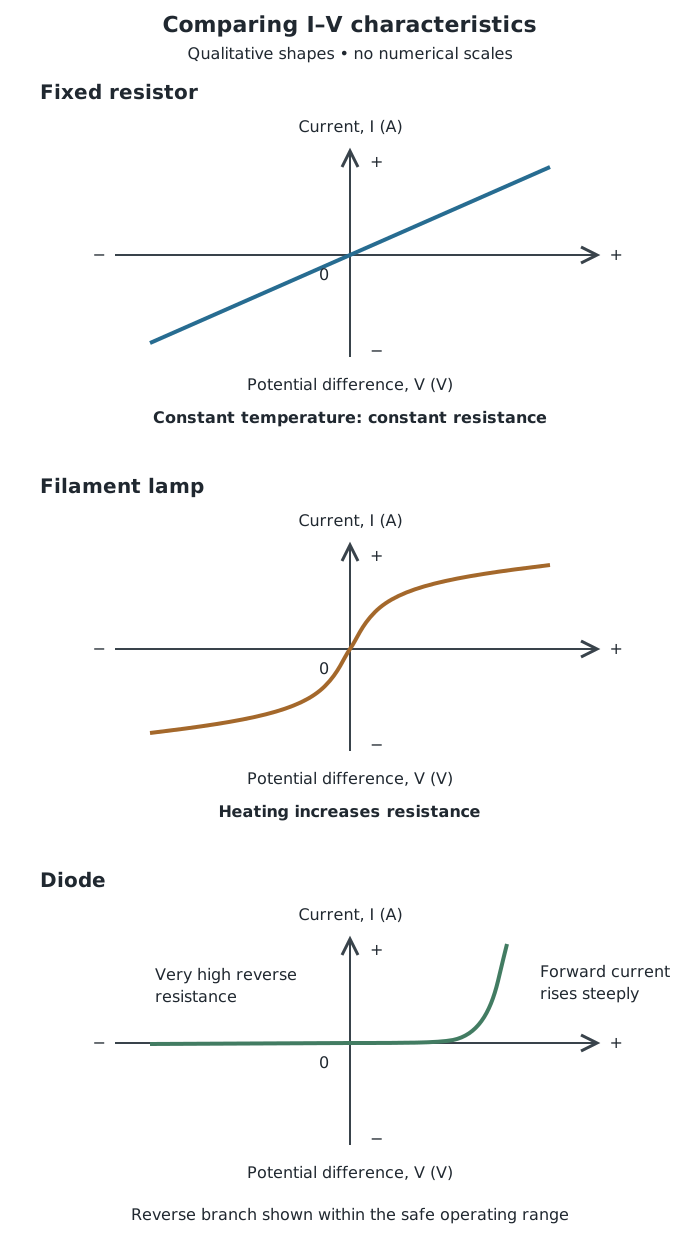
Characteristic shapes distinguish constant resistance, heating effects and one-way conduction. These sketches have no numerical scales.
To interpret a characteristic, first check the axes, then look for a straight line through the origin, curvature and any difference between the two directions. Link these observations to constant resistance, heating or one-way conduction rather than simply naming the shape.
Use a low-voltage d.c. supply, connecting leads, an ammeter, a voltmeter and the component being tested. A variable resistor in series provides a way to vary the current and the potential difference across the test component. Alternatively, a variable d.c. power supply can vary the potential difference directly.
The ammeter goes in series so it measures the current through the component. The voltmeter goes in parallel across the component so it measures the potential difference between its two terminals. Use that voltmeter reading, rather than the supply setting: other parts of the circuit may also have a potential difference across them.
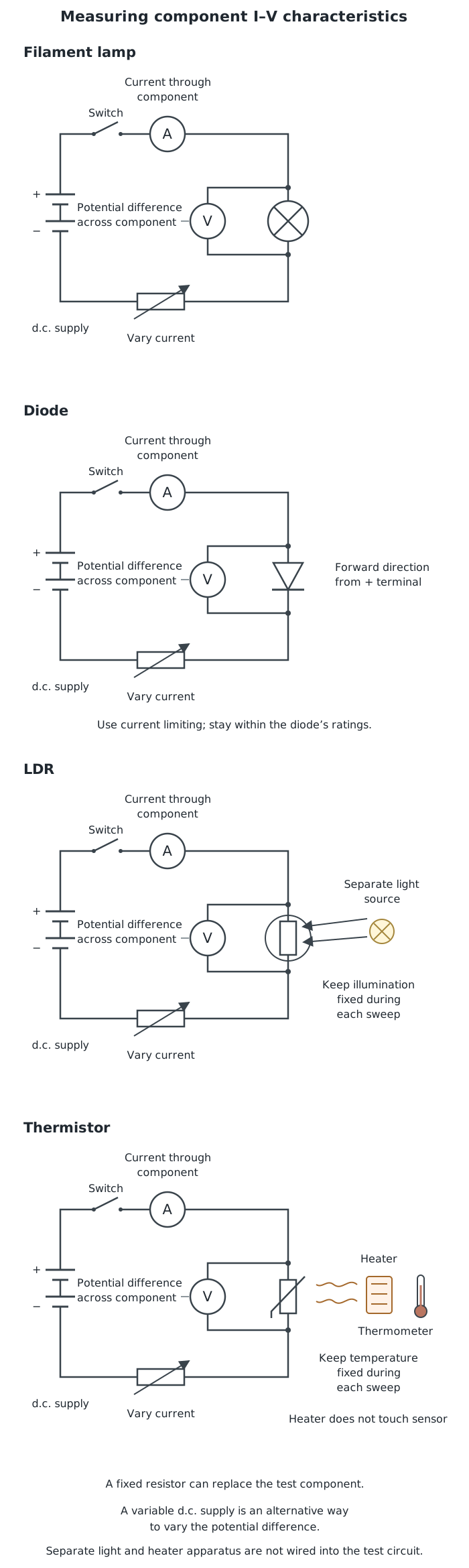
The measuring connections stay the same when the test component changes. Control light or temperature when investigating an LDR or thermistor.
Use the same arrangement for a fixed resistor, filament lamp or diode, replacing only the test component. For a fixed resistor, avoid appreciable heating so that its temperature stays approximately constant. For a lamp, let the readings settle at each setting so that the filament’s temperature is reasonably steady.
Use a current-limiting resistor or a suitably current-limited supply when testing a diode or LED. Do not exceed component ratings, including the permitted reverse potential difference. Lamps and resistors can become hot: switch off before changing components and allow them to cool before touching them. The investigation is complete when the readings cover the intended safe range and clearly establish the characteristic—not when a component overheats.
An LDR responds to light. Its resistance decreases as the light intensity reaching it increases. At the same potential difference, it therefore carries more current in brighter light. This makes it useful in light-sensitive circuits, such as automatic outdoor lighting.
A thermistor responds to temperature. For the type studied here, its resistance decreases as temperature increases. At the same potential difference, a warmer thermistor carries more current. This makes it useful in temperature-sensing circuits, such as electronic thermostats.
To investigate their I–V characteristics, put the LDR or thermistor in the test-component position in the same measuring circuit. For an LDR, keep the illumination fixed while varying the potential difference and recording paired and readings. Repeat at a different fixed illumination. A separate lamp can provide the light; keep other lighting conditions controlled and avoid heating the LDR.
For a thermistor, keep its temperature steady while collecting each set of paired readings. Repeat at a different temperature, using controlled external heating and a thermometer to monitor temperature. Keep the heater close but not touching the thermistor, allow time for the temperature and readings to settle, and take care around hot equipment. Use small measuring currents to minimise heating by the current itself.
Plot and compare the I–V graphs, and calculate at selected points. Brighter conditions should give a lower LDR resistance; warmer conditions should give a lower thermistor resistance. Whether an individual characteristic is linear must be judged from the graph under the stated conditions. An environmental change in resistance is not, by itself, proof that current and potential difference have a non-linear relationship at a fixed environment.
Check the axes before interpreting a graph. On an I–V graph, current is vertical and potential difference is horizontal.
A straight line through the origin shows direct proportionality. A straight line that does not pass through the origin does not.
For a straight-line I–V graph through the origin, a steeper gradient means a lower resistance.
Find resistance at a point using R = V/I. For a curved graph, do not treat the gradient of a tangent as I/V.
Draw the ammeter in series and the voltmeter in parallel across only the component being tested. Include a way to vary the current or potential difference.
When comparing LDR or thermistor results, state which environmental condition changes and which conditions are kept constant.
It can see this note and what your specification asks for.
Answers are free with an account.
1 free note left this week
Get more free notesYour answer sets when this note comes back for review, or marks it complete.
Was this note helpful?
Log in to tell us whether it helped, or to report a problem.
Last updated
Resistance
A measure of how much a component opposes electric current, calculated using and measured in ohms ().
I–V characteristic
A graph showing how the current through a component changes with the potential difference across it.
Linear circuit element
A circuit component whose current is directly proportional to the potential difference across it under constant physical conditions; its I–V graph is a straight line through the origin.
Non-linear circuit element
A circuit component whose current is not directly proportional to the potential difference across it; its I–V characteristic is not a straight line through the origin.
Diode
A component that allows current to flow readily in one direction but has a very high resistance in the opposite direction.
LDR
A light-dependent resistor whose resistance decreases as the light intensity reaching it increases.
Thermistor
A temperature-sensitive resistor. In the type studied here, resistance decreases as temperature increases.
Put your knowledge into practice — try past paper questions for Combined Science B
Resistance
A measure of how much a component opposes electric current, calculated using and measured in ohms ().
I–V characteristic
A graph showing how the current through a component changes with the potential difference across it.
Linear circuit element
A circuit component whose current is directly proportional to the potential difference across it under constant physical conditions; its I–V graph is a straight line through the origin.
Non-linear circuit element
A circuit component whose current is not directly proportional to the potential difference across it; its I–V characteristic is not a straight line through the origin.
Diode
A component that allows current to flow readily in one direction but has a very high resistance in the opposite direction.
LDR
A light-dependent resistor whose resistance decreases as the light intensity reaching it increases.
Thermistor
A temperature-sensitive resistor. In the type studied here, resistance decreases as temperature increases.
Use the coordinates of a point with non-zero current. Constant means constant resistance. For straight lines through the origin on I–V axes, steeper means lower resistance.