

Loading…
Loading…
Loading…
OCR GCSE Combined Science B · J260
OCR J260 · Circuit Quantities and Characteristics Check the specification (PDF) (opens in a new tab)
Metal wires and components already contain charged particles that are free to move. In metals, these moving particles are electrons. A cell or battery provides a potential difference, which causes these charges to move around the circuit when there is a complete conducting path.
Both a source of potential difference and a closed circuit are needed for a sustained current. Closing a switch completes the path; opening it breaks the path and stops the current in that loop.
Current is the rate of flow of charge: it tells us how much charge passes a point each second. A greater current means more charge passes each second, not simply that there is more charge stored in the wire. Current is measured in amperes, A, often called amps.
The battery supplies energy, not a stream of new electrons that components use up. Charge circulates continuously. In a single closed loop, the current therefore has the same value at every point, including before and after a lamp. The lamp transfers energy to its surroundings, but does not use up charge.
The quantity of charge passing a point depends on the current and how long it flows:
Here, is charge in coulombs (C), is current in amperes (A), and is time in seconds (s). One ampere means one coulomb of charge passes a point every second. For a constant current, doubling the time doubles the charge transferred.
To calculate charge, multiply current by time. To find either of the other quantities, rearrange the equation:
These equations distinguish the total charge transferred from its rate of flow. A small current flowing for a long time can transfer as much charge as a larger current flowing briefly.
Potential difference is the energy transferred per unit charge between two points. It is measured in volts (V) and is also called voltage. Across a component, it describes how much energy is transferred by each coulomb passing through it.
Resistance measures how strongly a component opposes current. It is measured in ohms (Ω). The current through a component depends on both its resistance and the potential difference across it:
Here, is potential difference in volts, is current in amperes, and is resistance in ohms. Rearranging gives:
At the same resistance, a greater potential difference produces a greater current. At the same potential difference, a greater resistance produces a smaller current. Keeping the other quantity constant is important when making either comparison.
For example, a current of through a resistor gives a potential difference of across it. Reading the same relationship in reverse, a potential difference of across that resistor produces a current of ; dividing the potential difference by the current gives its resistance, .
In a series circuit, components are connected end to end in one loop. A cell or battery supplies direct current, or d.c., which flows in one direction.
The same current passes through every component. The supply potential difference is shared between the components, so the potential differences across them add to the supply value:
The resistances in series also add:
To find the current through two series resistors, first add their resistances, then use . Once the current is known, use for each resistor to find its individual potential difference. A larger resistance has a larger potential difference across it because the current is the same through both.
Circuit diagrams show electrical connections using standard symbols rather than pictures of the apparatus. Lines represent connecting wires. Follow these lines to check whether there is a complete path through the components and back to the supply.
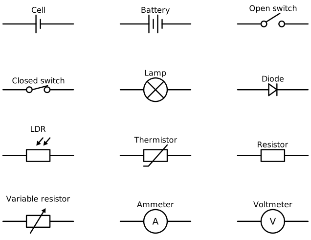
Standard circuit symbols identify components and their electrical roles.
A cell is shown by one long and one short parallel line: the long line is positive and the short line is negative. A battery contains more than one cell. Conventional current is shown flowing from the positive terminal to the negative terminal through the external circuit; electrons in metal wires move in the opposite direction.
A filament lamp has a circle containing a cross. A fixed resistor has a rectangular symbol; a variable resistor adds a diagonal arrow to show that its resistance can be adjusted. An open switch shows a gap, whereas a closed switch completes the connection.
A diode's symbol identifies its direction: it allows current mainly in one direction. An LDR, or light-dependent resistor, has arrows pointing towards it to represent incoming light. A thermistor's resistor symbol has a distinctive diagonal line with a short end stroke, identifying a temperature-sensitive component. These symbols allow you to recognise the components without needing to draw their physical appearance.
Resistance can be found by measuring the current through a wire and the potential difference across it, then calculating . To investigate how resistance depends on length, change the length of wire included in the circuit.
Use a suitable low-voltage power supply, an ammeter, a voltmeter, a switch, connecting leads, crocodile clips, uninsulated resistance wire, tape and a metre ruler. Tape the wire straight alongside the ruler. One clip stays at the zero mark; the other selects the length being tested.
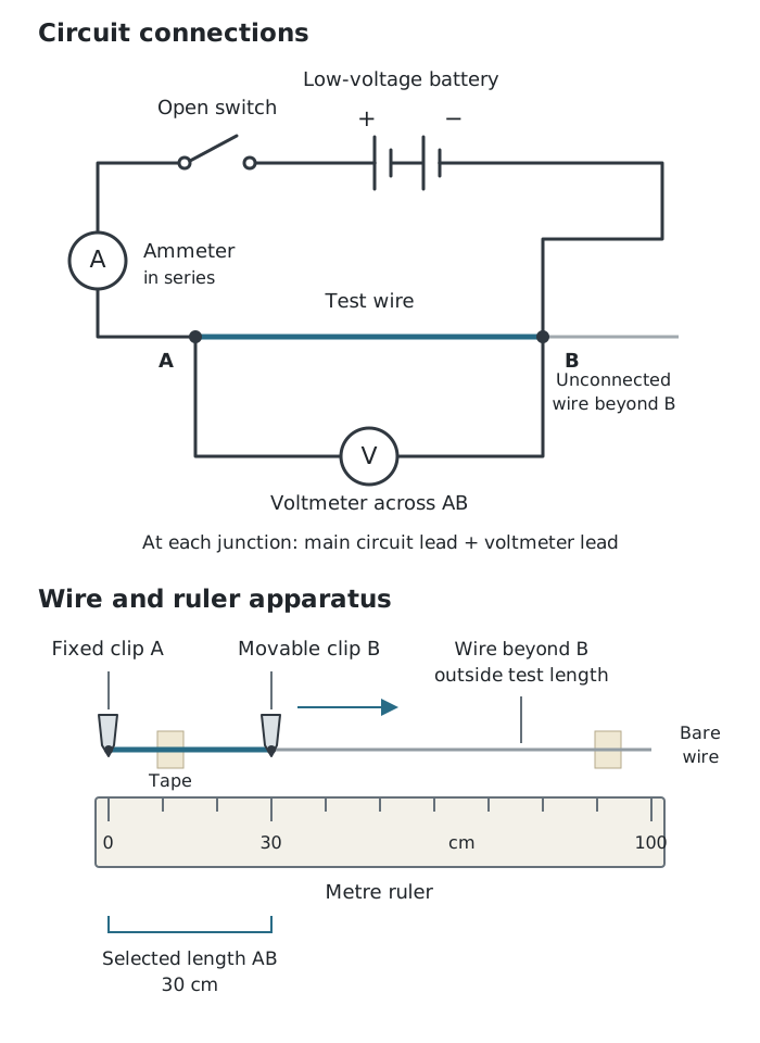
The ammeter measures current through the selected wire length; the voltmeter measures potential difference between its ends.
The ammeter is connected in series, so the current through the test wire passes through it. The voltmeter is connected in parallel across the selected wire length, with one connection at each clip. Its two connections let it measure the potential difference between the ends of that length.
Use the same wire throughout so its material and thickness remain constant. Keep its temperature as constant as possible by taking readings briefly and switching off between measurements. The uninsulated wire can become hot: avoid touching it during use and allow it to cool before handling or adjusting it.
A longer length of the same wire is expected to have a greater resistance. At a constant temperature, resistance is approximately proportional to length, giving a straight-line trend through the origin. The investigation is complete when readings cover a suitable range of lengths and repeats are sufficiently consistent to identify the trend.
Current flows through a component; potential difference is measured across it.
Convert time to seconds before using Q = It, and convert milliamperes to amperes before using V = IR.
Connect an ammeter in series and a voltmeter in parallel across the component being investigated.
For a whole series circuit, use the supply potential difference and the total resistance. For one component, use the potential difference across that component.
In the wire investigation, control temperature as well as the wire's material and thickness: heating can change its resistance.
It can see this note and what your specification asks for.
Answers are free with an account.
1 free note left this week
Get more free notesYour answer sets when this note comes back for review, or marks it complete.
Was this note helpful?
Log in to tell us whether it helped, or to report a problem.
Last updated
Current
The rate of flow of electric charge, measured in amperes (A). One ampere means one coulomb passes a point each second.
Charge
An electrical property carried by particles such as electrons. The quantity of charge transferred is measured in coulombs (C).
Potential difference
The energy transferred per unit charge between two points, measured in volts (V). Also called voltage.
Resistance
A measure of how strongly a component opposes current, measured in ohms (Ω). It is calculated using .
Closed circuit
A complete conducting path around which charge can flow.
Series circuit
A circuit in which components are connected end to end in a single loop, so the same current passes through every component.
Direct current
An electric current that flows in one direction.
Ammeter
An instrument that measures current in amperes and is connected in series with the component.
Voltmeter
An instrument that measures potential difference in volts and is connected in parallel across the component.
Put your knowledge into practice — try past paper questions for Combined Science B
Current
The rate of flow of electric charge, measured in amperes (A). One ampere means one coulomb passes a point each second.
Charge
An electrical property carried by particles such as electrons. The quantity of charge transferred is measured in coulombs (C).
Potential difference
The energy transferred per unit charge between two points, measured in volts (V). Also called voltage.
Resistance
A measure of how strongly a component opposes current, measured in ohms (Ω). It is calculated using .
Closed circuit
A complete conducting path around which charge can flow.
Series circuit
A circuit in which components are connected end to end in a single loop, so the same current passes through every component.
Direct current
An electric current that flows in one direction.
Ammeter
An instrument that measures current in amperes and is connected in series with the component.
Voltmeter
An instrument that measures potential difference in volts and is connected in parallel across the component.