

Loading…
Loading…
Loading…
Eduqas GCSE Design and Technology · C600
Eduqas C600 · Prototyping Techniques and Assembly Check the specification (PDF) (opens in a new tab)
A metal component usually begins as stock material: a standard form such as sheet, strip, rod or tube. The task is to turn that stock into a component with the correct outline, dimensions and features. For example, a metal bracket might need a cut outline, smooth edges, a bend and accurately positioned fixing holes.
Wastage means removing material to obtain the required shape. Sawing, drilling, turning and milling are examples: unwanted material is removed as offcuts or small pieces called swarf. This differs from an additive process, which builds up a shape by adding material, and from forming, which changes a piece's shape through forces such as bending. Turning and milling remove material; they do not reshape it by bending.
Accuracy depends on the whole sequence. A carefully drilled hole will still be in the wrong position if it was marked out incorrectly, and a correctly marked component can be spoiled if it moves during cutting.
Marking out transfers the required dimensions and shape onto the stock before work begins. A steel rule measures distances, while a try square helps establish lines at right angles to a straight edge. A tape measure is useful for larger lengths. Begin from a consistent reference edge so that related dimensions share the same starting point.
A scriber scratches fine layout lines onto the metal. Dividers can mark curves, and a centre punch makes a small indentation at a hole position to help locate the drill.
Before cutting, secure the metal in a vice or clamp. Holding prevents movement and keeps hands away from the cutting operation. Position the work so that the intended cut is accessible without leaving an unnecessarily long, unsupported section.
A hacksaw with a suitable metal-cutting blade is used for hand-cutting metal. A metal-cutting bandsaw can cut stock to length; its blade and operating conditions must suit the metal, and cutting fluid cools the cutting area. Tin snips cut very thin sheet metal, while a guillotine shears sheet metal with a heavy blade. Choose the tool to suit the stock's thickness and the required contour rather than treating every saw as interchangeable.
Check the cut against the marked outline and required dimensions. Cutting to length is not the same as producing a finished component: further shaping or machining may still be needed.
Use workshop equipment only with instruction and supervision. Wear eye protection where chips or swarf may be produced, secure the work and keep hands clear of cutting edges. Stop machinery before measuring, adjusting the work or clearing swarf.
An engineer's file removes small amounts of metal to shape an edge, adjust a fit or remove burrs. A burr is a sharp raised edge left after cutting or drilling. Secure the component in a vice and use a file fitted with a sound handle. File towards the marked outline, checking frequently so that too much material is not removed. The operation is complete when the required dimensions and contour are reached and sharp burrs have been removed.
Emery paper or wet-and-dry abrasive paper can then smooth the surface. Work from coarser to finer grades as needed; wrapping the abrasive around a flat block helps maintain a flat surface. Smoothing cannot correct an incorrectly sized component, so check dimensions before concentrating on its appearance.
Bending changes the shape without cutting away the main body of the metal. For a simple bracket, mark the bend position, clamp the metal in a vice or between folding bars, and bend the projecting section to the required angle. Folding bars hold sheet along the bend line. A former provides a shaped support around which metal can be bent, helping several pieces achieve the same shape. An anvil provides a firm surface for hammering and forming; its curved horn can support curved work.
Keep fingers clear of the bend and hammering area, secure the work and wear eye protection. Check the finished angle and dimensions against the design or former, and inspect for cracks or unwanted distortion. The bend is finished when the required shape is achieved, not merely when the metal has moved.
A pillar drill produces holes using a drill bit held in a rotating chuck. Different bit diameters produce different hole diameters. The workpiece is supported on the table and secured, commonly in a machine vice; it must not be held loosely by hand because the rotating bit can catch and turn it.
Locate the required hole position, select the appropriate metal drill bit and secure the work. Check that the bit is aligned with the intended position before drilling. If the chuck uses a key, remove it before starting. Use the guard and wear eye protection. Tie back long hair and keep loose clothing and jewellery away from rotating parts; do not wear gloves near rotating machinery.
A jig locates the work and guides drilling, making hole positions more consistent. A former can support a shaped component so that it sits correctly during drilling. These devices are useful when several components need matching features: positioning each piece in the same way reduces variation.
Use the speed and cutting conditions specified for the metal and bit. Drill with controlled feed until the required depth or through-hole has been produced. Stop the machine before removing the work, then check the hole's position and diameter and remove burrs. Clear sharp swarf with a suitable brush, not with bare fingers. A hole is successful only if it meets the component's requirements, not merely because the bit has passed through.
Holes are designed for different jobs. Their diameters and entrance shapes affect how a screw or bolt fits.
A pilot hole is a small guide hole used before a subsequent operation, such as inserting a screw. Its diameter must suit that operation; it is not automatically a clearance hole or a tapping hole.
A clearance hole lets a screw or bolt pass through without its thread gripping the material. This allows the fastener to connect with another threaded part or a nut.
A tapping hole is drilled before an internal thread is cut using a tap. It must be smaller than the thread's outside diameter so that material remains for the tap to cut. Select the drilling diameter for the chosen thread size and pitch rather than guessing it.
To tap the hole, secure the component in a vice, prepare the hole entrance with a small chamfer and hold the tap in a tap wrench. Apply suitable cutting lubricant and keep the tap perpendicular to the surface. Turn it to cut the thread, reversing periodically to break the chips. Once the required threaded depth has been reached, wind the tap out, clear the swarf safely and check that the intended screw engages correctly. Forcing a misaligned tap risks breaking it.
A countersunk hole has a tapered recess at its entrance, made with a countersink cutter after drilling. A matching countersunk screw head fits into this recess so that its top can sit flush with the surface.
A counterbored hole has an enlarged cylindrical entrance with a flat-bottomed recess, produced with a suitable counterboring cutter. It accommodates a suitable fastener head below or level with the surrounding surface. Check recess depth against the chosen head; its straight-sided recess is different from the taper of a countersink.
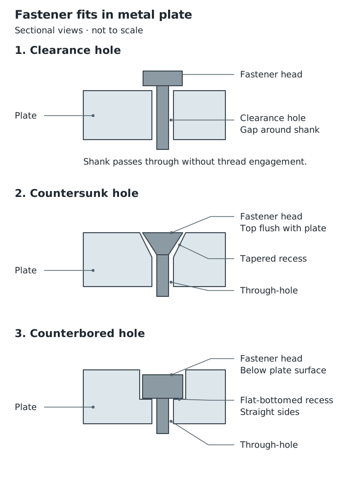
The entrance shape determines how the fastener head fits: a countersink is tapered, while a counterbore has a flat-bottomed recess.
For a bracket, a clearance hole might allow a bolt to pass through. If a projecting head would interfere with another part, the design may require a countersink or counterbore suited to the chosen head. Select the hole alongside the fastener, not as an afterthought.
A centre lathe rotates the workpiece while a cutting tool removes material. The workpiece can be held in a three-jaw chuck, and the cutting tool is secured in a tool post and moved using the machine's slides; it is not held by hand.
Facing removes material from the end face to make it flat and smooth. Parallel turning removes material from the outside, reducing the diameter over a selected length. Turning only part of that length can leave a step called a shoulder. Progress is checked against the required length and diameter, with the machine stopped before measuring.
A milling machine uses rotating cutters to remove material from a held workpiece. The work is clamped securely in a machine vice attached to the table. Moving the table relative to the cutter controls where material is removed, while vertical adjustment controls cutting depth. Milling can create a slot or machine a flat face or edge.
For a slot, select a suitable cutter, position it at the required location and move the work relative to it along the slot's length. Check the finished width, length and depth. To face an edge, remove material in controlled passes until the required flat surface and dimension are achieved.
The important distinction is what rotates: on a lathe, the workpiece rotates; in milling, the cutter rotates. This explains why a lathe is particularly useful for round components, while a mill produces features such as slots in a block.
For both machines, secure the work and tooling, use guards and eye protection, and keep clear of moving parts. Tie back hair, remove loose jewellery and do not wear gloves near rotating parts. Use the correct tool and speed for the task, and stop before checking dimensions or removing swarf. Isolate the machine as instructed before changing tooling. Completion means that the specified dimensions and surface have been achieved, not simply that a machining pass has ended.
Computer-aided manufacture (CAM) uses computer-controlled equipment to carry out manufacturing operations. It can produce cut features, engrave surfaces and mark positions for holes or fixings. Accurate manufacture still depends on a suitable design, correct settings and secure positioning of the material.
A laser uses a concentrated beam to cut, engrave or mark material. Most school laser cutters cannot cut metal; suitably powerful industrial machines can. Capability and settings must suit the metal and its thickness. Unsuitable settings can cause damage or an incomplete cut.
Before manufacture, check the intended outline, dimensions and feature positions. Operate laser equipment only under the workshop's approved procedures, with its protective enclosure and safety systems in use. After processing, check that cuts are complete and that features are correctly positioned and sized.
For a metal prototype, CAM can help produce features that align with other components. It does not replace inspection: a precisely repeated mistake is still a mistake.
Link each tool or machine to the feature it produces: a lathe produces turned round forms; a milling machine can produce slots and flat faces.
Distinguish a clearance hole, which lets a screw pass freely, from a tapping hole, which is prepared to receive an internal thread.
A countersink has a tapered recess; a counterbore has a cylindrical recess with a flat bottom.
When explaining accuracy, identify how the work is located, held and checked rather than simply saying that a machine is accurate.
Do not assume that every laser cutter can cut metal. Its capability and settings must suit the material and thickness.
It can see this note and what your specification asks for.
Answers are free with an account.
1 free note left this week
Get more free notesYour answer sets when this note comes back for review, or marks it complete.
Was this note helpful?
Log in to tell us whether it helped, or to report a problem.
Last updated
Wastage
Manufacturing by cutting or removing material from stock to obtain the required shape.
Marking out
The process of transferring dimensions and the required shape onto material before manufacture.
Jig
A device that locates work and guides a tool so that an operation can be carried out accurately and repeatedly.
Former
A shaped support or template used to establish or maintain a required form.
Pillar drill
A drilling machine with a supported, rotating drill bit and a table on which the workpiece can be secured.
Pilot hole
A small-diameter guide hole, used before a subsequent operation such as inserting a screw.
Clearance hole
A hole large enough for a screw or bolt to pass through without its thread engaging with the material.
Tapping hole
A hole drilled to a suitable diameter before a tap cuts an internal screw thread.
Tap
A cutting tool used to cut an internal screw thread in a prepared hole.
Countersunk hole
A hole with a tapered recess at its entrance, allowing a matching screw head to sit flush with the surface.
Counterbored hole
A hole with an enlarged cylindrical entrance and a flat-bottomed recess that accommodates a fastener head.
Burr
A sharp raised edge left on metal after an operation such as cutting or drilling.
Turning
Machining in which the workpiece rotates against a cutting tool to produce round forms.
Milling
Machining in which a rotating cutter removes material from a securely held workpiece, for example to produce a slot or flat face.
Computer-aided manufacture
The use of computer-controlled equipment to carry out manufacturing operations.
Put your knowledge into practice — try past paper questions for Design and Technology
Wastage
Manufacturing by cutting or removing material from stock to obtain the required shape.
Marking out
The process of transferring dimensions and the required shape onto material before manufacture.
Jig
A device that locates work and guides a tool so that an operation can be carried out accurately and repeatedly.
Former
A shaped support or template used to establish or maintain a required form.
Pillar drill
A drilling machine with a supported, rotating drill bit and a table on which the workpiece can be secured.
Pilot hole
A small-diameter guide hole, used before a subsequent operation such as inserting a screw.
Clearance hole
A hole large enough for a screw or bolt to pass through without its thread engaging with the material.
Tapping hole
A hole drilled to a suitable diameter before a tap cuts an internal screw thread.
Tap
A cutting tool used to cut an internal screw thread in a prepared hole.
Countersunk hole
A hole with a tapered recess at its entrance, allowing a matching screw head to sit flush with the surface.
Counterbored hole
A hole with an enlarged cylindrical entrance and a flat-bottomed recess that accommodates a fastener head.
Burr
A sharp raised edge left on metal after an operation such as cutting or drilling.
Turning
Machining in which the workpiece rotates against a cutting tool to produce round forms.
Milling
Machining in which a rotating cutter removes material from a securely held workpiece, for example to produce a slot or flat face.
Computer-aided manufacture
The use of computer-controlled equipment to carry out manufacturing operations.
Secure work, use guards and eye protection, remove chuck keys and keep hair, clothing and hands clear of rotating parts. Do not wear gloves near rotating machinery. Stop before measuring or clearing swarf; use a brush for chips. Check dimensions, hole positions, recess depths, complete cuts and surface quality.