

Loading…
Loading…
Loading…
Edexcel GCSE Design and Technology · 1DT0
Edexcel 1DT0 · 4b Check the specification (PDF) (opens in a new tab)
A 2D form is flat: it has two dimensions, such as width and height. A 3D form has width, height and depth. A rectangular face is 2D; a box with rectangular faces is 3D.
Drawing a box on paper does not make the paper three-dimensional. Instead, the lines represent its depth. Designers need to move between these representations: imagining a solid object from flat views, then drawing it so another person can understand its shape.
Different drawings communicate different information. A client may need to understand what a product will look like, while someone making it needs clear shapes and dimensions. One drawing does not always do both jobs equally well.
An isometric drawing shows width, height and depth together. It is useful for explaining the overall form of a product because several faces can be seen at once.
To draw a box, begin with its nearest corner. Draw one edge vertically upwards and two edges at 30° to the horizontal, one to the left and one to the right. These establish the three main directions. Mark the required lengths along them using the same drawing scale, then complete the faces with parallel lines.
Unlike perspective, edges do not converge as they recede. The far edges of a rectangular box remain parallel to the corresponding near edges.
For a more complicated product, lightly sketch a surrounding box first. This technique, called crating, helps establish the overall proportions before adding details such as a sloping top or rounded corner. Keep the construction lines light and make the finished outline clear.
Orthographic projection represents a solid using separate flat views. Each view looks squarely at the object rather than showing it at an angle:
Suppose a rectangular box is 60 mm wide, 40 mm deep and 30 mm high. Its front view is a 60 mm by 30 mm rectangle; its plan is 60 mm by 40 mm; its side is 40 mm by 30 mm. These are three views of one box, not three separate parts.
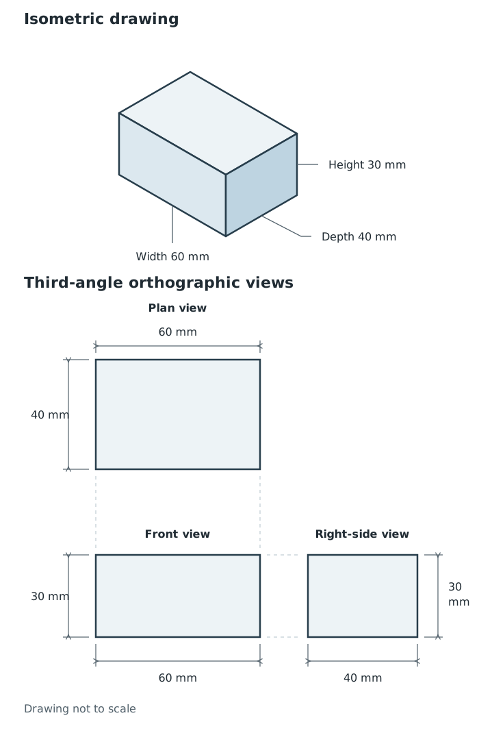
One box represented in two ways: isometric shows its overall form, while aligned orthographic views separate its dimensions.
To visualise the solid, connect the information across the views. The plan tells you how far the front face extends backwards. The side confirms the height and depth. A front rectangle alone cannot tell you whether the object is a shallow panel or a deep box.
In a third-angle arrangement, the plan is above the front view and the right-side view is to its right. Corresponding edges line up: width aligns between front and plan, while height aligns between front and side. Keeping these relationships consistent helps another person reconstruct the same shape you intended.
Dimensions communicate actual sizes rather than leaving the reader to estimate from the drawing. Where an edge is hidden behind a surface, dashed lines can show its position. Orthographic views are therefore particularly useful when communicating information for manufacture.
A perspective drawing represents how an object appears from a particular viewpoint. Features further away appear smaller. Sets of parallel edges running away from the viewer converge towards vanishing points on a horizon line, which represents eye level.
In one-point perspective, the front face of a box faces the viewer directly. Draw that face as a rectangle, place a vanishing point on the horizon, then draw light lines from the corners towards it. Choose where the back of the box will lie and complete its back edges with horizontal and vertical lines. Strengthen the visible outline and remove unnecessary construction lines.
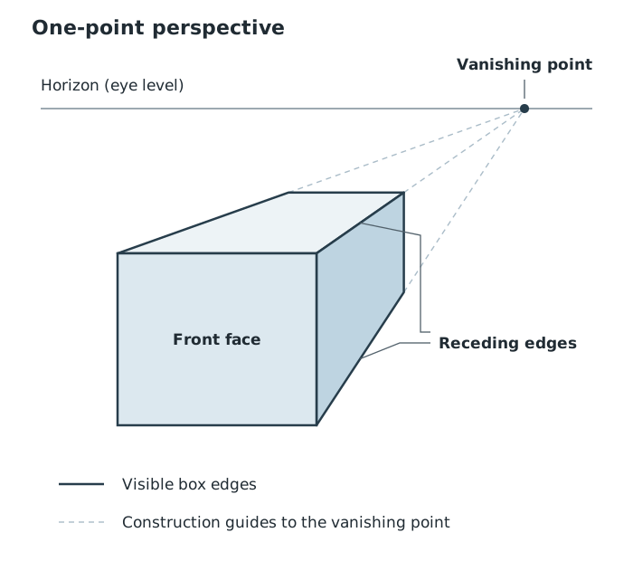
In one-point perspective, edges running away from the viewer converge towards the same vanishing point.
Two-point perspective is useful when looking towards a corner: the two sets of horizontal edges recede towards different vanishing points, while vertical edges remain vertical.
Perspective can help a client imagine a finished product, but apparent lengths change with depth. It is not a substitute for dimensioned views when exact sizes are needed.
A quick freehand sketch is useful for exploring an idea before committing to a precise drawing. Aim first for recognisable shape and sensible proportions. Shading can help distinguish faces and make the form easier to understand, but it should not obscure edges or details.
Add annotations to explain information that the shape alone cannot communicate. For a storage box, a note pointing to the lid could explain that it is removable so the contents are easy to reach. Other notes might identify a material, a dimension or a surface finish. Connect each note clearly to the feature it describes.
If the important question is how parts fit together, an exploded view separates them while keeping their relative positions and assembly direction clear. If you need to inspect an idea from several angles, a 3D CAD model can be rotated on screen and edited as the design develops.
Choose the method to suit the intention: an isometric sketch for overall form, perspective for appearance, orthographic views for shape and size, or an exploded view for assembly.
Choose the view for its purpose. Use clear outlines, consistent proportions, dimensions where needed and annotations explaining relevant features. CAD allows drawings and 3D models to be edited and inspected.
Use the views together: front and plan share width; front and side share height; plan and side share depth.
In an isometric drawing, keep vertical edges vertical and draw the two receding directions at 30° to the horizontal. Parallel edges must remain parallel.
When asked to communicate an idea through sketches, use clear drawings and annotations pointing to the relevant features.
Choose a representation that answers the question: appearance, accurate shape and size, or assembly.
It can see this note and what your specification asks for.
Answers are free with an account.
1 free note left this week
Get more free notesYour answer sets when this note comes back for review, or marks it complete.
Was this note helpful?
Log in to tell us whether it helped, or to report a problem.
Last updated
2D form
A flat shape or representation with two dimensions, such as width and height.
3D form
An object with three dimensions: width, height and depth.
Isometric drawing
A pictorial drawing showing three dimensions, with vertical edges vertical and the other two main directions at 30° to the horizontal.
Orthographic projection
A drawing method using separate flat views, usually front, plan and side, to describe the shape and dimensions of a three-dimensional object.
Plan view
A view of an object looking directly down from above.
Perspective drawing
A drawing that represents depth by making objects appear smaller with distance and directing receding parallel edges towards vanishing points.
Annotation
A short note attached to a drawing to explain a feature, dimension, material or design decision.
CAD
Computer-aided design: the use of computer software to create and edit drawings or digital models.
Put your knowledge into practice — try past paper questions for Design and Technology
2D form
A flat shape or representation with two dimensions, such as width and height.
3D form
An object with three dimensions: width, height and depth.
Isometric drawing
A pictorial drawing showing three dimensions, with vertical edges vertical and the other two main directions at 30° to the horizontal.
Orthographic projection
A drawing method using separate flat views, usually front, plan and side, to describe the shape and dimensions of a three-dimensional object.
Plan view
A view of an object looking directly down from above.
Perspective drawing
A drawing that represents depth by making objects appear smaller with distance and directing receding parallel edges towards vanishing points.
Annotation
A short note attached to a drawing to explain a feature, dimension, material or design decision.
CAD
Computer-aided design: the use of computer software to create and edit drawings or digital models.