Loading…


Loading…
Loading…
Loading…
Edexcel GCSE Combined Science · 1SC0
Edexcel 1SC0 · Circuit components and energy transfer Check the specification (PDF) (opens in a new tab)
A series circuit has one continuous loop. The same current passes through every component because there is no junction at which it can divide. Potential difference tells us how much energy is transferred per coulomb of charge. The supply potential difference is shared between the components, so their potential differences add up to the supply value.
For two resistors in series:
Use for the whole circuit or for an individual component. Keep the quantities matched: the potential difference across one resistor must be paired with the current through that resistor and its resistance.
For example, connect a resistor and a resistor in series to a supply. Their total resistance is , so the current is everywhere in the loop. The potential differences are and . Together these make the supply's .
The larger resistor has the larger potential difference because both carry the same current. If its resistance were unknown, it could be found from .
To investigate a component, we need to measure both the current through it and the potential difference across it. An ammeter goes in series, so the component's current passes through the meter. A voltmeter goes in parallel across the component, so it measures the potential difference between its two ends.
A useful testing circuit contains a low-voltage d.c. supply, a switch, an ammeter, a variable resistor and the test component. The variable resistor changes the current and therefore the potential difference across the test component. The switch lets us disconnect the circuit between readings or while changing components.
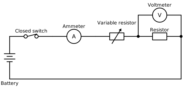
The ammeter measures the current through the test resistor. The voltmeter measures only the potential difference across that resistor.
Construct the circuit with the supply switched off. Begin with a high resistance on the variable resistor to limit the current, then switch on and adjust it gradually. Use short connecting leads with negligible resistance and stay within the ratings of the components. Disconnect the supply before altering connections, and avoid touching a hot lamp.
This design deliberately puts the ammeter and current-controlling components in the same loop as the test component. The voltmeter must span only the component being tested, not the variable resistor as well.
In the core practical, first use a fixed resistor as the test component. Adjust the variable resistor to obtain a range of potential differences. At each setting, record the voltmeter reading in volts and the ammeter reading in amperes, then calculate:
Repeat readings to check consistency. Keep the resistor's temperature as constant as possible by using suitable small currents and switching off between readings if it becomes warm. Reverse the supply connections and repeat to obtain readings for the opposite current direction.
Replace the resistor with a filament lamp and repeat the investigation. Allow the readings to settle at each setting as the filament reaches its operating temperature. Heating is part of the lamp's behaviour, but the lamp must not be driven beyond its rating.
Plot current on the vertical axis and potential difference on the horizontal axis. These I–V characteristics show whether current is proportional to potential difference and whether resistance remains constant.
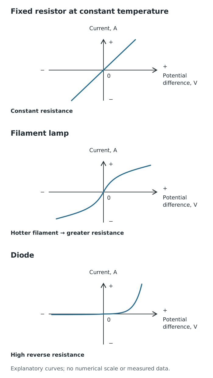
Qualitative I–V characteristics: a resistor has constant resistance at constant temperature, a lamp's resistance increases as it heats, and a diode behaves differently in the two directions.
For a fixed resistor at constant temperature, the graph is a straight line through the origin. Doubling the potential difference doubles the current, so stays constant. A steeper straight line represents a lower resistance because more current flows for the same potential difference.
For a filament lamp, increasing the potential difference increases the current and heats the filament. Its resistance rises as its temperature rises, so current increases less rapidly at larger potential differences. The graph bends and becomes less steep. Reversing the supply reverses the current, giving a corresponding curve on the negative side. Calculate at different points to show the changing resistance.
A diode behaves differently in the two directions. In the forward direction, little current flows at small potential differences; once the potential difference is sufficient, the current rises rapidly. In the reverse direction, its resistance is very high and the current is approximately zero over the normal testing range.
To investigate a diode, use the same meter arrangement with a series resistance to limit the current. Take readings as the potential difference changes, then reverse the diode or supply and repeat. Use small adjustments where the forward current rises quickly. The two sides of its graph demonstrate its strongly direction-dependent resistance.
The core practical also involves constructing and testing series and parallel circuits using resistors and filament lamps. Begin with one resistor connected to a supply, with an ammeter in series and a voltmeter across the resistor. Record the supply potential difference and current.
Add a second resistor in series, keeping the supply potential difference unchanged. Measure the current at different positions by moving the ammeter with the supply switched off. Measure the potential difference across each resistor and across the pair. The current should be the same at each position, and the two component potential differences should add to the supply value. Calculating total resistance from the supply potential difference divided by the supply current shows that the added resistor increases total resistance.
Reconnect the two resistors in parallel, with each branch connected between the same two supply terminals. Measure the total current before the junction and each branch current by placing the ammeter in the appropriate path. Measure the potential difference across each branch. Both branches have the supply potential difference, while their currents add to the total current. The extra path increases total current at the same supply potential difference, showing that total resistance has decreased.
Repeat these arrangements using filament lamps. With two identical lamps and the same supply potential difference, lamps in series are dimmer than a single lamp because they share the supply potential difference. In parallel, each receives the full supply potential difference and is approximately as bright as the single lamp. Use meter readings, not brightness alone, to test the circuit relationships.
Opening a series loop stops current through every component. Opening just one parallel branch leaves the other branch complete. This explains why parallel branches can be controlled independently.
An LDR responds to light: its resistance is high in darkness and decreases as light intensity increases. This makes it useful as a sensor in automatic lighting circuits.
Put the LDR into the testing circuit with an ammeter in series and a voltmeter across it. Illuminate it with a lamp and change the illumination by adjusting the lamp's brightness or distance. At each setting, wait for stable readings and calculate . Keep the electrical supply and other conditions unchanged, and avoid warming the LDR with the illuminating lamp. If light intensity is measured, plot resistance against it; otherwise, compare resistance at the different illumination settings.
A negative temperature coefficient thermistor responds to temperature: its resistance decreases as temperature increases. This is the type of thermistor considered here, and it can be used in temperature-sensing circuits.
Use the same electrical measuring arrangement, placing a suitable thermistor in a water bath with a thermometer. Change the water temperature by adding warm water, stir to make the temperature uniform, and allow the thermistor to reach the water temperature before recording temperature, current and potential difference. Keep electrical connections dry and use a sufficiently small current to minimise heating by the measuring circuit itself. Calculate resistance at each temperature and plot resistance against temperature. The graph falls as temperature rises.
Get unlimited access to all revision notes, key terms, and exam tips.
Change illumination for an LDR or measured temperature for a thermistor. Keep other conditions constant, allow readings to stabilise, measure and , and calculate resistance at each setting.
Get unlimited access to all revision notes, key terms, and exam tips.
Connect an ammeter in series with the component and a voltmeter in parallel across it.
In series, current is the same everywhere, but potential difference is shared; it is not necessarily shared equally.
Calculate resistance at a particular operating point using R = V/I. Do not treat the gradient of a curved I–V graph as 1/R.
For a fair comparison of series and parallel arrangements, keep the supply potential difference and the components unchanged.
Reversing the supply gives negative potential differences and currents on an I–V graph; these signs indicate direction.
Moving a lamp changes the illumination of an LDR, but distance is not itself a measurement of light intensity.
Current
The rate of flow of electric charge, measured in amperes (A).
Potential difference
The energy transferred per unit charge between two points, measured in volts (V).
Resistance
A measure of how strongly a component opposes current, calculated using and measured in ohms (Ω).
Series circuit
A circuit in which components are connected end to end in one loop, so the same current passes through each component.
Parallel circuit
A circuit with separate branches connected between the same two points, providing more than one path for current.
I–V characteristic
A graph showing how the current through a component changes with the potential difference across it.
Diode
A component that allows appreciable current in one direction but has very high resistance in the opposite direction.
LDR
A light-dependent resistor whose resistance decreases as the light intensity falling on it increases.
Negative temperature coefficient thermistor
A temperature-sensitive resistor whose resistance decreases as its temperature increases.
Put your knowledge into practice — try past paper questions for Combined Science
Current
The rate of flow of electric charge, measured in amperes (A).
Potential difference
The energy transferred per unit charge between two points, measured in volts (V).
Resistance
A measure of how strongly a component opposes current, calculated using and measured in ohms (Ω).
Series circuit
A circuit in which components are connected end to end in one loop, so the same current passes through each component.
Parallel circuit
A circuit with separate branches connected between the same two points, providing more than one path for current.
I–V characteristic
A graph showing how the current through a component changes with the potential difference across it.
Diode
A component that allows appreciable current in one direction but has very high resistance in the opposite direction.
LDR
A light-dependent resistor whose resistance decreases as the light intensity falling on it increases.
Negative temperature coefficient thermistor
A temperature-sensitive resistor whose resistance decreases as its temperature increases.