Loading…


Loading…
Loading…
Loading…
AQA GCSE Combined Science Trilogy · 8464
AQA 8464 · 6.2.1.4 Resistors and Circuit Components Check the specification (PDF) (opens in a new tab)
Current is the rate of flow of electric charge through a component, measured in amperes (A). Potential difference is the energy transferred per unit charge between two points, measured in volts (V). Resistance describes how strongly a component opposes current and is measured in ohms ().
These quantities are linked by:
To find a component’s resistance, measure the potential difference across it and the current through it, then use . For example, a reading of 4 V across a resistor with a current of 0.20 A gives a resistance of .
A single pair of readings tells you the resistance under those conditions. To discover whether the resistance stays constant, you need readings over a range of potential differences. Plotting these gives the component’s I–V characteristic.
For an ohmic conductor at constant temperature, current is directly proportional to potential difference. Doubling the potential difference doubles the current; tripling it triples the current. The ratio therefore stays the same, so the resistance is constant.
A suitable fixed resistor behaves this way as long as its temperature remains constant. A variable resistor lets you deliberately adjust the resistance; once its setting is fixed, it can also behave as an ohmic conductor at constant temperature.
On a graph with potential difference on the horizontal axis and current on the vertical axis, an ohmic conductor produces a straight line through the origin. It is a linear component. Reversing the potential difference reverses the current, giving the same straight-line relationship in the negative region.
For this choice of axes, the gradient is . A steeper line means more current for the same potential difference, so it represents a lower resistance.
A filament lamp contains a thin metal wire. Current heats the filament until it emits light. As the current increases, the filament becomes hotter and its resistance increases.
At a higher temperature, the atoms in the metal vibrate more strongly. Electrons moving through the filament encounter more collisions, making it harder for charge to flow. Increasing the potential difference still increases the current, but the current increases less rapidly as the filament gets hotter.
The lamp’s I–V graph therefore curves and becomes less steep at larger potential differences. It is non-linear: current and potential difference are not directly proportional. Reversing the potential difference reverses the current, but the filament heats in either direction, so the curve has a matching shape in the negative region.
A diode allows current to flow in one direction only. Connected in the conducting direction, it is forward biased. At small forward potential differences, very little current flows; as the potential difference increases sufficiently, the current rises sharply.
Connected in the opposite direction, it is reverse biased. Its resistance is very high, so the current is effectively zero over the range used in this investigation. This one-way behaviour is useful when a circuit needs to prevent current flowing in the wrong direction.
A diode’s I–V graph is non-linear and, unlike the lamp’s graph, is not symmetrical about the origin. The forward side rises sharply, whereas the reverse side lies very close to the horizontal axis.
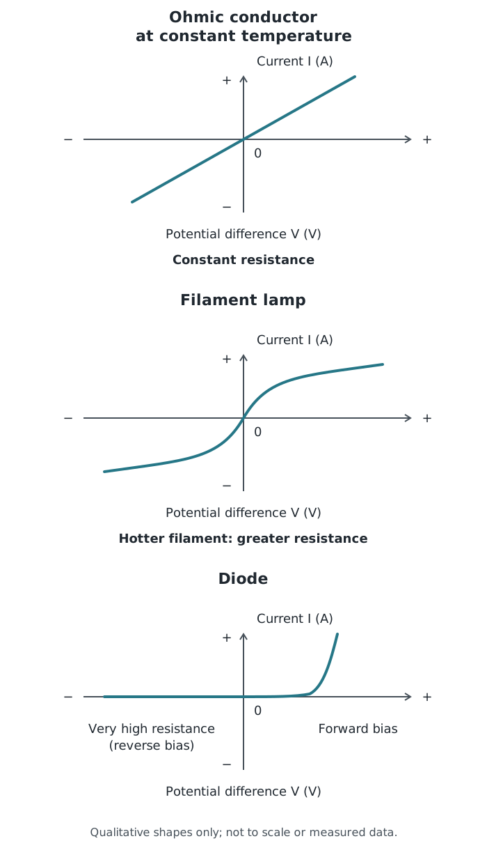
Qualitative I–V characteristics. The axes have the same orientation in every panel; the curves show behaviour.
Other components, including thermistors and light-dependent resistors (LDRs), also have resistance that is not always constant. Their responses to temperature and light are considered separately.
To investigate resistance, you need a low-voltage d.c. supply, connecting leads, an ammeter, a voltmeter, a variable resistor and the component being tested.
The ammeter goes in series with the component so it measures the current passing through it. The voltmeter goes in parallel across the component so it measures the potential difference between the component’s two ends. The variable resistor is in series and allows you to change the current and the potential difference across the test component. An adjustable d.c. supply can also be used to vary the potential difference.
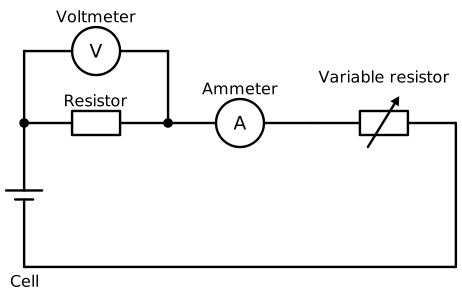
The ammeter and variable resistor are in series with the test resistor. The voltmeter measures the potential difference across the test resistor alone.
When drawing the circuit, use standard symbols: a rectangle for a resistor, a rectangle with a diagonal arrow for a variable resistor, and circles containing A and V for the meters. Keep the voltmeter connected across the test component when replacing the resistor with a lamp or diode.
The investigation compares a resistor at constant temperature, a filament lamp and a diode.
Components and wires can become hot. Disconnect the supply when not taking readings, switch off before changing connections, and allow hot components to cool before handling them. Excessive potential difference or current can damage components.
Plot current against potential difference for each component, with labelled axes and units. Draw a suitable best-fit line or smooth curve rather than joining every point with straight segments.
A straight line through the origin supports constant resistance and ohmic behaviour under the conditions tested. A lamp curve that becomes less steep shows that current is increasing less rapidly as the filament heats. A diode curve with negligible reverse current and a sharp forward rise shows its one-way conducting behaviour.
You can also calculate at different non-zero points. Equal ratios indicate constant resistance; changing ratios indicate changing resistance. This connects the graph’s shape to the measurements rather than relying only on recognising a familiar outline.
Get unlimited access to all revision notes, key terms, and exam tips.
: volts; : amperes; : ohms.
Ammeter in series; voltmeter in parallel across the test component. Vary the potential difference using a variable resistor or adjustable supply.
Get unlimited access to all revision notes, key terms, and exam tips.
Always include ‘at constant temperature’ when explaining why an ohmic conductor has constant resistance.
Connect the ammeter in series and the voltmeter in parallel across the component being tested, not across the whole circuit.
Check the axes before interpreting a graph. With current on the vertical axis and potential difference on the horizontal axis, a steeper straight line means a lower resistance.
For a non-linear component, calculate resistance at a particular point using R = V/I. Do not use the gradient of a tangent as its resistance.
Explain the filament lamp curve as a chain: greater current → hotter filament → greater resistance → current increases less rapidly.
A diode can have a potential difference across it in reverse bias even though the current is effectively zero.
Resistance
A measure of how strongly a component opposes current, calculated using and measured in ohms ().
Ohmic conductor
A conductor whose current is directly proportional to the potential difference across it, provided its temperature remains constant.
Direct proportion
A relationship in which multiplying one quantity by a factor multiplies the other by the same factor. Its graph is a straight line through the origin.
I–V characteristic
A graph showing how the current through a component varies with the potential difference across it.
Linear component
A component whose current–potential difference graph is a straight line through the origin, showing constant resistance under the conditions tested.
Non-linear component
A component whose current–potential difference graph is not a single straight line, so current and potential difference are not directly proportional.
Filament lamp
A lamp containing a thin metal wire that becomes hot enough to emit light when current passes through it.
Diode
A component that allows current to flow in one direction only and has a very high resistance in the reverse direction.
Put your knowledge into practice — try past paper questions for Combined Science Trilogy
Resistance
A measure of how strongly a component opposes current, calculated using and measured in ohms ().
Ohmic conductor
A conductor whose current is directly proportional to the potential difference across it, provided its temperature remains constant.
Direct proportion
A relationship in which multiplying one quantity by a factor multiplies the other by the same factor. Its graph is a straight line through the origin.
I–V characteristic
A graph showing how the current through a component varies with the potential difference across it.
Linear component
A component whose current–potential difference graph is a straight line through the origin, showing constant resistance under the conditions tested.
Non-linear component
A component whose current–potential difference graph is not a single straight line, so current and potential difference are not directly proportional.
Filament lamp
A lamp containing a thin metal wire that becomes hot enough to emit light when current passes through it.
Diode
A component that allows current to flow in one direction only and has a very high resistance in the reverse direction.