Loading…


Loading…
Loading…
Loading…
AQA GCSE Combined Science Trilogy · 8464
AQA 8464 · 6.2.1.3 Current, Resistance and Potential Difference Relationship Check the specification (PDF) (opens in a new tab)
Resistance describes how strongly a component opposes electric current. This practical investigates two ways of changing resistance: changing the length of a wire, and arranging resistors in series or in parallel.
To find resistance, measure the current through the component with an ammeter and the potential difference across it with a voltmeter. Current is the rate of flow of charge; potential difference, also called voltage, measures the energy transferred per unit charge. Calculate resistance using:
Here, is potential difference in volts (V), is current in amperes (A), and is resistance in ohms (). Measuring both quantities matters: a current reading alone does not tell you the resistance unless you also know the potential difference.
The first investigation asks how the resistance of a wire changes with its length at constant temperature. Use a battery or suitable low-voltage power supply, an ammeter, a voltmeter, connecting leads, crocodile clips and a thin resistance wire, such as constantan or nichrome, taped alongside a metre ruler.
One crocodile clip stays at the zero end of the wire. Moving the second clip changes the length of wire included in the circuit. Only the section between the two clip contacts is being tested.
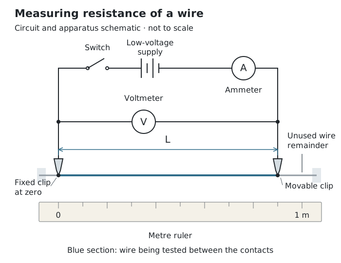
Moving one clip changes the tested length. Measure current through that section and potential difference across it.
The ammeter is connected in series with the tested wire, so the current through the wire passes through it. The voltmeter is connected across the two clip contacts, so it measures the potential difference across that same section.
Set up and check the circuit with the supply switched off. Trace the current path from the supply through the ammeter and tested wire back to the supply, then check that the voltmeter spans the tested section.
A results table needs columns for length, potential difference, current and calculated resistance, with units in the headings: cm or m, V, A and respectively.
The independent variable is the length between the clips. The dependent variable is the calculated resistance. Use the same wire throughout to keep its material and thickness unchanged, and keep the power-supply setting unchanged.
Temperature must also remain as constant as possible because heating changes the wire's resistance. Use a low potential difference, switch off between readings and allow the wire to cool. Short sections have low resistance, so they can carry a large current and become especially hot. Avoid touching the wire while it is powered or still hot, and switch off before moving connections.
Plot resistance on the vertical axis and wire length on the horizontal axis, then draw a line of best fit. For a uniform wire at constant temperature, resistance is directly proportional to length: doubling the length doubles the resistance. The expected graph is a straight line through the origin.
A longer section provides a longer conducting path, so it offers more resistance. This comparison is meaningful only when the material, thickness and temperature stay unchanged.
Real results may not pass exactly through the origin. A clip placed slightly away from the ruler's zero can introduce a length zero error. Resistance at the contacts can also contribute to the measured resistance. Check the contact positions and make secure connections rather than assuming every departure from the ideal graph is caused by the wire itself.
The second investigation changes the arrangement of two resistors while keeping the resistors themselves the same. Use two equal resistors, for example two wire-wound resistors, with a battery or suitable power supply, switch, ammeter, voltmeter, connecting leads and crocodile clips. Wire-wound resistors help reduce overheating problems.
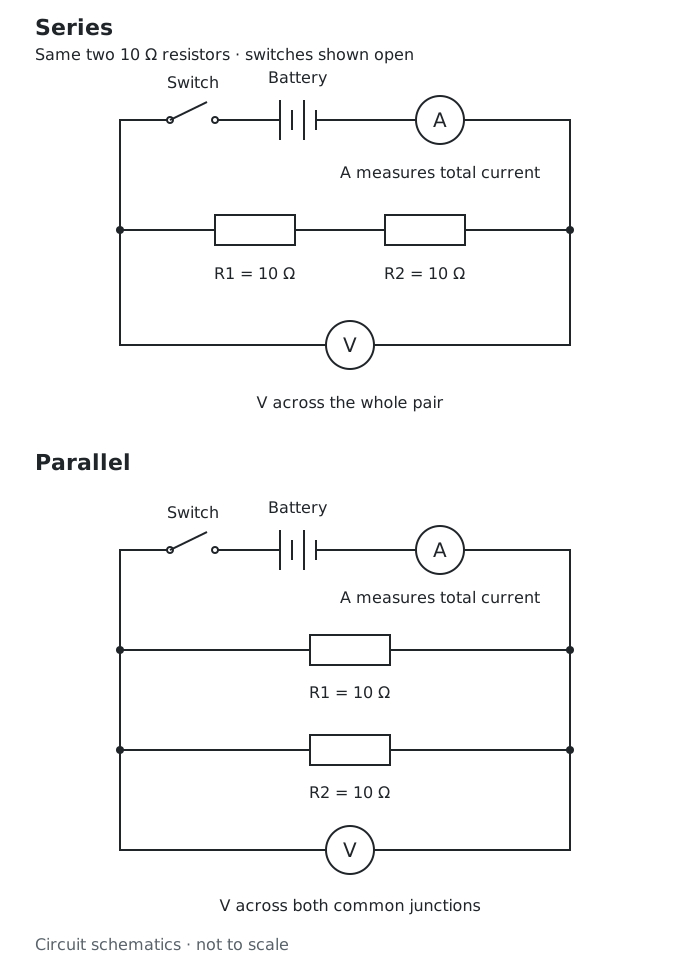
Use the same two resistors in both arrangements. The meters measure the potential difference and total current needed to calculate the combined resistance.
First connect the resistors in series. The ammeter measures the current through both resistors, and the voltmeter spans the whole pair. Check the circuit against the diagram, close the switch briefly and record the readings. Calculate the total resistance using .
Open the switch before reconnecting the same resistors in parallel. The ammeter must now be in the main supply path, before the current divides or after it rejoins, so it measures total current, not just one branch current. The voltmeter connects across the two points shared by both branches. Check the connections, take readings and calculate the total resistance again. Repeat measurements to check that the comparison is consistent, keeping the supply setting and resistor temperature as steady as possible.
In series, there is one path through both resistors. Their resistances add:
Two resistors therefore have an expected total resistance of in series.
In parallel, the branches provide alternative paths for current. Each resistor has the same potential difference across it, but the supply delivers current to both branches. The total resistance is lower than either individual resistance. For two equal resistors, it is half the resistance of one: two resistors have an expected total resistance of in parallel.
The measured potential difference may differ slightly between arrangements, so compare the calculated resistances rather than the current readings alone.
Get unlimited access to all revision notes, key terms, and exam tips.
in ; in V; in A.
Use the same two equal resistors in both arrangements; measure total current and potential difference across the whole pair.
Get unlimited access to all revision notes, key terms, and exam tips.
An ammeter measures current through a component and goes in series; a voltmeter measures potential difference across it and goes in parallel.
Measure the wire length between the crocodile-clip contact points, not the total length of wire attached to the ruler.
Explain temperature control: heating changes resistance, so it would prevent a fair test of length alone.
For a resistor combination, use the total current and the potential difference across the whole combination in R = V/I.
Describe resistance as directly proportional to wire length only when material, thickness and temperature are unchanged.
Resistance
A measure of how strongly a component opposes electric current, measured in ohms (). It can be calculated using .
Current
The rate of flow of electric charge, measured in amperes (A).
Potential difference
The energy transferred per unit charge between two points in a circuit, measured in volts (V). Also called voltage.
Series circuit
An arrangement in which components are connected one after another along a single current path.
Parallel circuit
An arrangement in which components are connected on separate branches between the same two points.
Control variable
A quantity kept unchanged during an investigation so that its effect does not interfere with the relationship being tested.
Zero error
A measurement error caused by a reading or reference position being displaced from its correct zero.
Put your knowledge into practice — try past paper questions for Combined Science Trilogy
Resistance
A measure of how strongly a component opposes electric current, measured in ohms (). It can be calculated using .
Current
The rate of flow of electric charge, measured in amperes (A).
Potential difference
The energy transferred per unit charge between two points in a circuit, measured in volts (V). Also called voltage.
Series circuit
An arrangement in which components are connected one after another along a single current path.
Parallel circuit
An arrangement in which components are connected on separate branches between the same two points.
Control variable
A quantity kept unchanged during an investigation so that its effect does not interfere with the relationship being tested.
Zero error
A measurement error caused by a reading or reference position being displaced from its correct zero.