Loading…


Loading…
Loading…
Loading…
AQA GCSE Combined Science Trilogy · 8464
AQA 8464 · 6.2.1.4 Resistors and Circuit Components Check the specification (PDF) (opens in a new tab)
Resistance describes how strongly a component opposes electric current. At the same potential difference, a component with a higher resistance carries a smaller current. A thermistor responds to temperature, while a light-dependent resistor (LDR) responds to light intensity. Their changing resistance allows circuits to detect changes in their surroundings.
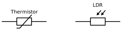
Compare the thermistor and LDR symbols. The LDR’s inward-pointing arrows represent light reaching it.
For the thermistors studied here, resistance decreases as temperature increases. A cold thermistor has a higher resistance than the same thermistor when warm. If the potential difference across it stays constant, warming it therefore increases the current through it.
This is the opposite of the temperature effect in a metal filament: a filament lamp’s resistance increases as its filament becomes hotter.
A thermistor can act as the temperature sensor in a thermostat. As a room warms, the thermistor’s resistance falls. The control circuit detects this change and switches the heater off when the chosen temperature is reached. As the room cools, the resistance rises and the circuit can switch the heater back on. The thermistor supplies the temperature-dependent signal; the surrounding circuit controls the heater.
An LDR’s resistance decreases as light intensity increases. It has a high resistance in darkness and a lower resistance in bright light. At a constant potential difference across the LDR, brighter light produces a larger current through it.
An automatic outdoor light uses an LDR to detect darkness. As daylight fades, the LDR’s resistance increases. A control circuit responds to this change by switching the light on. When daylight returns, the resistance falls and the circuit switches the light off. The circuit is arranged to give the desired response: the LDR does not itself act as a simple mechanical switch.
A direct method uses a thermistor, an ohmmeter or multimeter set to measure resistance, connecting leads, crocodile clips, a beaker of warm water and a thermometer. The ohmmeter measures resistance directly, so no separate power supply is connected to the thermistor.
Temperature is the independent variable; resistance is the dependent variable. Use the same thermistor throughout. Plot temperature on the horizontal axis and resistance on the vertical axis.
Reading the graph from lower to higher temperature, resistance falls. Over a sufficiently wide temperature range, the graph is usually curved rather than straight: equal temperature increases need not produce equal resistance decreases. This graph can also be used as a calibration curve. A later resistance reading can be matched to the curve to estimate the thermistor’s temperature.
Connect an LDR to an ohmmeter using leads and crocodile clips. Illuminate it with a lamp whose brightness can be adjusted, keeping the lamp at a fixed distance and orientation.
Begin with the lamp off in a dim room and record the resistance. Increase the lamp’s brightness in stages, allowing the LDR’s reading to settle each time. Record the light setting and resistance at each stage, then repeat to check the pattern.
Keep background lighting as constant as possible and avoid casting a shadow over the LDR. Keep the lamp close enough to illuminate the sensor but not touching it, and avoid heating the LDR: the investigation should change light conditions, not temperature.
The expected pattern is brighter light → lower resistance. Lamp settings provide a comparison of relative light levels, not calibrated measurements of light intensity. A resistance–light intensity graph generally falls non-linearly; resistance does not necessarily decrease by equal amounts for equal increases in light intensity.
Instead of using an ohmmeter, resistance can be calculated from measurements of current and potential difference. Connect an ammeter in series with the sensor and a voltmeter in parallel across it.
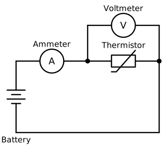
The ammeter measures current through the thermistor; the voltmeter measures potential difference across it. Replace the thermistor with an LDR to investigate light intensity.
The thermistor can be replaced by an LDR to investigate light intensity. Change the relevant environmental condition, wait for stable readings and record both meters at each stage. Calculate each resistance using:
Here, is the potential difference across the sensor in volts, is the current through it in amperes and is its resistance in ohms. Use a low-voltage supply and avoid excessive current, which could heat the sensor and affect the investigation.
Get unlimited access to all revision notes, key terms, and exam tips.
Ammeter in series; voltmeter in parallel across the sensor. Measure in volts and in amperes to obtain in ohms.
Get unlimited access to all revision notes, key terms, and exam tips.
State the direction of the change: increasing temperature decreases thermistor resistance; increasing light intensity decreases LDR resistance.
For an automatic light, explain that darkness increases the LDR’s resistance and the control circuit responds by switching the light on. Do not claim that increased resistance directly makes a lamp brighter.
When measuring resistance using current and potential difference, connect the ammeter in series and the voltmeter in parallel across the sensor.
An LDR symbol has arrows pointing towards it, representing incoming light.
A falling curve does not show inverse proportionality unless the data establish that specific relationship.
Resistance
A measure of how strongly a component opposes electric current, measured in ohms (Ω). It can be calculated using .
Thermistor
An electrical component whose resistance changes with temperature. For the thermistors studied here, resistance decreases as temperature increases.
LDR
A light-dependent resistor: an electrical component whose resistance decreases as the light intensity reaching it increases.
Thermostat
A device that controls heating or cooling to maintain a chosen temperature.
Ohmmeter
A meter that measures electrical resistance directly, in ohms (Ω).
Calibration curve
A graph relating a sensor’s readings to known values of the quantity being measured, allowing later readings to be interpreted.
Put your knowledge into practice — try past paper questions for Combined Science Trilogy
Resistance
A measure of how strongly a component opposes electric current, measured in ohms (Ω). It can be calculated using .
Thermistor
An electrical component whose resistance changes with temperature. For the thermistors studied here, resistance decreases as temperature increases.
LDR
A light-dependent resistor: an electrical component whose resistance decreases as the light intensity reaching it increases.
Thermostat
A device that controls heating or cooling to maintain a chosen temperature.
Ohmmeter
A meter that measures electrical resistance directly, in ohms (Ω).
Calibration curve
A graph relating a sensor’s readings to known values of the quantity being measured, allowing later readings to be interpreted.