Loading…


Loading…
Loading…
Loading…
AQA GCSE Design and Technology · 8552
AQA 8552 · Shaping and forming techniques Check the specification (PDF) (opens in a new tab)
Electronic and mechanical systems need parts that fit together accurately. Cutting brings a part to the required size, drilling creates holes, and soldering joins suitable metal surfaces. Cutting and drilling remove material; soldering adds material to make a joint.
A useful electronic example is a printed circuit board (PCB). Its insulating base supports components, while copper tracks provide conducting paths between them. In a through-hole assembly, component leads pass through drilled holes and are soldered to copper connections on the other side.
In a mechanical system, a metal shaft might need cutting to length, while a mounting bracket needs accurately positioned holes for its fixings. The material, dimensions and purpose of each part determine the tools and technique used.
A PCB must fit its intended position without losing any tracks or component connections. Plan the board outline so that cutting removes surplus board rather than part of the circuit.
Tin snips can trim suitable thin circuit-board material. Cut carefully around the planned outline, then smooth rough edges where necessary. Tool choice must suit the board material and thickness: a method suitable for one thin board is not automatically suitable for every PCB.
Check the finished edge and nearby tracks. Removing too much material can break a conducting path, leaving components disconnected even if they have been soldered correctly.
A hacksaw can cut a metal shaft for a small mechanism. Measure the required length and mark the cut line with a scriber. Clamp the shaft firmly in a bench vice, keeping the cut close to the jaws so the unsupported section does not move excessively.
Choose a blade suited to the metal and section thickness. Its teeth should face forwards, away from the handle, because the cutting stroke is the forward push. The tooth spacing should allow at least three teeth to contact the metal during cutting, rather than individual teeth catching on the work.
Start a shallow groove with short, gentle strokes. Once the blade is guided by the groove, use long strokes, applying pressure on the forward stroke and reducing it on the return. As the cut nears completion, slow down and reduce pressure to avoid tearing the metal and leaving a large sharp burr. Check the finished length before assembling the mechanism.
For through-hole components, the hole positions must match the spacing of their leads. Accurate positioning allows the leads to pass through the board without being forced and leaves copper around each hole for soldering.
Use a small PCB drill with a bit appropriate to the lead diameter. A drill stand or drill press improves control and helps keep the bit perpendicular to the board. Secure the board on a flat sacrificial backing board so it cannot move; the backing supports it as the drill breaks through.
Align the bit with the intended hole position and feed it gently through the board. Let the drill cut rather than forcing it: small bits break easily. Wear eye protection and use the equipment under appropriate workshop supervision.
Many PCBs have a fibreglass base. This is abrasive and can quickly wear ordinary high-speed steel bits when many holes are drilled; specialist carbide bits are used for this work.
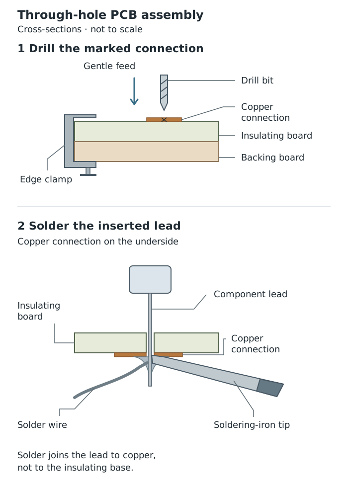
Through-hole assembly: drill an accurately positioned hole, then solder the component lead to the copper connection.
A bracket's fixing holes must line up with the parts it will support. Mark out the hole centres accurately. On a smooth metal such as steel, make a small indentation at each centre with a centre punch to help locate the drill and prevent it wandering at the start.
Select a suitable twist drill, such as a high-speed steel bit for mild steel, with a diameter appropriate to the fixing. For a large hole, drill a smaller pilot hole first to guide the larger bit.
Hold the bracket in a machine vice secured to the drill table. Do not hold the metal directly in your hand: the drill can catch as it breaks through and spin the workpiece. With eye protection and appropriate supervision, align the drill with the marked centre and feed it steadily through the metal without forcing it. Check the hole positions and fit before assembly.
The shared principle in PCB and bracket drilling is accurate positioning and secure support. Their hole sizes and tools differ because one receives component leads while the other receives mechanical fixings.
Soft soldering uses a filler metal that melts and flows over the joint surfaces. The component lead and copper connection remain solid. Once the solder cools, it holds the lead in place and provides an electrical connection.
For a through-hole joint:
Use an iron stand and suitable fume extraction, and keep fingers clear of the hot tip and newly heated joint. Work with the circuit power disconnected.
Soldering is not limited to circuit boards: an electric iron can also join small sections of suitable metals, such as copper or brass. The same principles apply—clean surfaces, close contact and enough heat for solder to flow across the joint.
One useful preparation is tinning, where each surface receives a thin coating of solder. Bringing the coated surfaces together and reheating them allows the solder layers to join. Larger metal sections conduct heat away more quickly, so a small electric iron may not supply enough heat.
For electronics, use appropriate electronics flux rather than corrosive active flux intended for other metalworking tasks. A sound joint depends on both suitable materials and a suitable joining process.
Get unlimited access to all revision notes, key terms, and exam tips.
Cutting and drilling remove material. Soldering adds a filler metal to make a joint, providing both attachment and electrical connection in a PCB assembly.
Get unlimited access to all revision notes, key terms, and exam tips.
Link the process to its purpose: cutting sets the size, drilling makes holes, and soldering joins metal parts.
When explaining soldering, include cleaning, heating both joint surfaces, applying solder and allowing the joint to cool.
Do not describe soldering as melting the component lead or copper track: the solder melts.
Choose a drill diameter to suit the component lead or fixing; there is no single correct diameter for every hole.
Explain workholding: a bench vice supports metal during sawing; a secured machine vice prevents a metal part spinning during drilling.
Printed circuit board
A board with conducting copper tracks that connect electronic components and an insulating base that supports them.
Through-hole technology
A method of mounting electronic components by passing their leads through holes in a circuit board and soldering them to its copper connections.
Soft soldering
Joining metal surfaces using a melted filler metal called solder, without melting the parts being joined.
Flux
A substance that helps remove surface oxides and allows molten solder to flow over the metal surfaces being joined.
Tinning
Coating a metal surface with a thin layer of solder before making a joint.
Put your knowledge into practice — try past paper questions for Design and Technology
Printed circuit board
A board with conducting copper tracks that connect electronic components and an insulating base that supports them.
Through-hole technology
A method of mounting electronic components by passing their leads through holes in a circuit board and soldering them to its copper connections.
Soft soldering
Joining metal surfaces using a melted filler metal called solder, without melting the parts being joined.
Flux
A substance that helps remove surface oxides and allows molten solder to flow over the metal surfaces being joined.
Tinning
Coating a metal surface with a thin layer of solder before making a joint.