

Loading…
Loading…
Loading…
OCR GCSE Combined Science A · J250
OCR J250 · P6 Check the specification (PDF) (opens in a new tab)
A circuit needs a source of potential difference, such as a cell or power supply, and a complete conducting path. Closing a switch completes that path; opening it breaks the path.
Current is the rate at which electric charge flows, measured in amperes (A). Potential difference, also called voltage, is the energy transferred per unit charge between two points, measured in volts (V). Resistance describes how strongly a component opposes current, measured in ohms (Ω).
These quantities are connected by:
Measuring the potential difference across a component and the current through it lets you calculate its resistance:
For example, suppose a resistor has a potential difference of 3.0 V across it and a current of 0.20 A through it. Its resistance is . For a lamp or diode, the calculated resistance can change as the operating conditions change: one reading does not necessarily describe the component at every voltage.
Circuit diagrams show electrical connections using standard symbols, rather than showing what the apparatus looks like on the bench. Follow the wires and junctions to decide which components share a path and which are on separate branches.
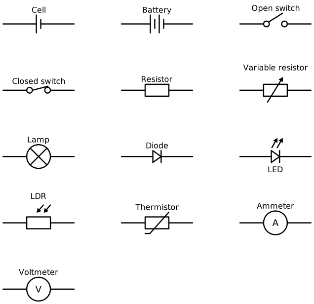
Standard symbols identify components independently of their appearance on the bench.
A cell supplies potential difference; a battery contains two or more cells. A switch opens or closes a path. A fixed resistor limits current, while a variable resistor has an adjustable resistance. A filament lamp transfers electrical energy to light and heating.
A diode allows current in one direction only. An LED is a light-emitting diode. Conventional current travels from the positive terminal towards the negative terminal through the external circuit, so diode orientation matters.
Some components respond to their surroundings: an LDR’s resistance decreases as light intensity increases, and the thermistor used in school circuits has a resistance that decreases as temperature increases. These provide other ways to explore changing resistance.
An ammeter goes in series with the component: charge passing through the component must also pass through the ammeter. A voltmeter goes in parallel across the component, with one lead connected to each end. It compares those two points rather than measuring along the whole circuit.
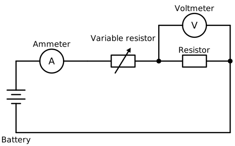
The ammeter measures current through the test resistor; the voltmeter measures potential difference across it. Replace the test resistor with a lamp or diode to investigate another component.
The variable resistor changes the current and therefore the potential difference across the test component. The voltmeter measures the actual potential difference across that component; it need not equal the power supply setting.
Build the circuit with the supply switched off. Trace the complete main loop, then check that the voltmeter leads connect to opposite ends of the test component. Check meter polarity, suitable ranges and whether the meters read zero before taking measurements. Start with a low supply setting and have the connections checked before switching on.
Use a low-voltage d.c. supply, connecting leads, an ammeter, a voltmeter, a variable resistor and the component under investigation. A fixed resistor, filament lamp and diode provide useful contrasting examples.
Keep the same component and connecting equipment throughout each set of readings. For the fixed resistor, keep its temperature as constant as possible by using small currents and switching off between readings.
Plot mean current on the vertical axis against potential difference on the horizontal axis. The investigation is complete when you have enough readings across both polarities to identify the characteristic shape, rather than just a single resistance value.
A fixed resistor at constant temperature gives a straight line through the origin. Doubling its potential difference doubles its current, so remains constant. This is Ohm’s law. On the same axis scales, a steeper straight line represents a smaller resistance because more current flows at a given voltage.
A filament lamp gives a curved graph. Current is not directly proportional to potential difference, so its resistance is not constant across the readings. It is a non-ohmic conductor.
A diode also has a non-ohmic characteristic: its graph is not a straight line through the origin. Unlike the resistor and lamp, it allows current in only one direction. Reversing the supply therefore lets you investigate its direction-dependent behaviour as well as how its current changes with potential difference.
Begin with one fixed resistor, measure its current and potential difference, and calculate its resistance. Repeat for a second resistor separately. You can then compare their individual resistances with the resistance of the pair.
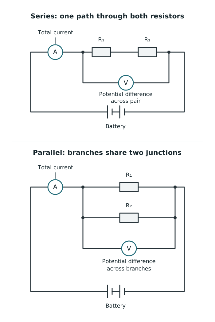
Measure total current and potential difference across the whole resistor arrangement to find its total resistance.
For a series circuit, connect the two resistors end to end in one main loop. Put the ammeter in that loop and the voltmeter across the whole pair to calculate total resistance. You can then move the voltmeter, with the supply switched off, to measure across each resistor separately.
The same current passes through both resistors. Their potential differences add to the potential difference across the pair, and their resistances add:
For a parallel circuit, connect each resistor in a separate branch between the same two junctions. An ammeter before the junction measures total current; an ammeter placed within a branch measures only that branch’s current. Each branch has the same potential difference, and the branch currents add to the total current.
Calculate the pair’s resistance using the potential difference across the branches divided by the total current. It should be less than either resistor’s individual resistance: the extra branch gives charge another route.
Check the physical circuit against the diagram by tracing each path from one supply terminal to the other. A component is not in parallel merely because it sits beside another on the bench: both ends must connect to the same two junctions. Repeat the comparison using filament lamps, measuring resistance at each operating condition rather than assuming it is constant.
Keep liquids away from electrical apparatus. Avoid touching wires or components while the circuit is operating: wires carrying large currents and filament lamps can become hot. Switch off between readings and before rewiring, and allow hot components to cool before handling them. If you smell burning or see unexpected overheating, switch off immediately and tell the teacher.
Avoid a direct wire connection across the supply, which could allow a dangerously large current. Stay within the ratings of the supply, meters and components.
Use repeated readings to identify inconsistent results and reduce random uncertainty. Check for zero errors before starting. Unwanted heating can change resistance during a measurement, while real meters can slightly affect the circuit. These effects help explain why measured values may not agree perfectly with the simple circuit model.
Vary potential difference using a variable resistor. Record paired voltage and current readings, repeat and average, then reverse supply polarity for negative readings. Plot current against potential difference.
Series: one path; same current throughout; potential differences add; .
Parallel: separate branches between the same junctions; same potential difference across each branch; branch currents add; total resistance is less than either individual resistance.
For total resistance, use the potential difference across the whole arrangement and its total current.
Check connections, polarity, meter ranges and zero readings. Switch off before rewiring and between readings; avoid short circuits and allow hot components to cool.
Connect an ammeter in series and a voltmeter in parallel across the component being tested.
Calculate resistance using the potential difference across a component and the current through that same component.
On an I–V graph, put potential difference on the horizontal axis and current on the vertical axis. Include units.
A fixed resistor obeys Ohm’s law only while its temperature remains constant.
Draw clear standard circuit symbols and straight connecting wires. Make branch junctions unambiguous.
Repeating readings helps reduce random uncertainty; it does not remove a meter’s zero error.
It can see this note and what your specification asks for.
Answers are free with an account.
1 free note left this week
Get more free notesYour answer sets when this note comes back for review, or marks it complete.
Was this note helpful?
Log in to tell us whether it helped, or to report a problem.
Last updated
Current
The rate of flow of electric charge, measured in amperes (A).
Potential difference
The energy transferred per unit charge between two points, measured in volts (V). Also called voltage.
Resistance
A measure of how strongly a component opposes current, calculated using and measured in ohms (Ω).
Ammeter
An instrument that measures current and is connected in series with the component being tested.
Voltmeter
An instrument that measures potential difference and is connected in parallel across the component being tested.
Series circuit
A circuit in which components are connected along one path, so the same current passes through them.
Parallel circuit
A circuit with separate branches connected between the same two junctions.
I–V characteristic
A graph showing how the current through a component changes with the potential difference across it.
Ohmic conductor
A conductor for which current is directly proportional to potential difference at constant temperature.
Put your knowledge into practice — try past paper questions for Combined Science A
Current
The rate of flow of electric charge, measured in amperes (A).
Potential difference
The energy transferred per unit charge between two points, measured in volts (V). Also called voltage.
Resistance
A measure of how strongly a component opposes current, calculated using and measured in ohms (Ω).
Ammeter
An instrument that measures current and is connected in series with the component being tested.
Voltmeter
An instrument that measures potential difference and is connected in parallel across the component being tested.
Series circuit
A circuit in which components are connected along one path, so the same current passes through them.
Parallel circuit
A circuit with separate branches connected between the same two junctions.
I–V characteristic
A graph showing how the current through a component changes with the potential difference across it.
Ohmic conductor
A conductor for which current is directly proportional to potential difference at constant temperature.