

Loading…
Loading…
Loading…
OCR GCSE Combined Science A · J250
OCR J250 · P3.2k Check the specification (PDF) (opens in a new tab)
A testing circuit lets us change the conditions around a component and measure its response. A low-voltage , such as a cell or battery, drives in one direction around the circuit. The measurements tell us how a component behaves, rather than simply whether it works.
Two measurements are particularly useful: the current through the component and the potential difference across it. Current is the rate of flow of charge; potential difference is the energy transferred per unit charge between two points.
An ammeter goes in series with the test component. This places it in the same current path, so it measures the current passing through that component. A voltmeter goes in parallel, with one connection at each end of the component. It measures the potential difference between those two points.
A variable resistor in series allows the current to be adjusted without replacing the component or changing the supply. Increasing its resistance reduces the current. Adjusting it also changes the potential difference across the test component.
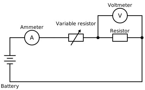
The ammeter measures the current through the test resistor; the voltmeter measures the potential difference across it. The variable resistor adjusts the test conditions.
The resistor shown is the test component. It can be replaced with a filament lamp, diode, LDR or thermistor while keeping the same basic meter arrangement. The variable resistor is a separate component used to control the circuit.
For each setting, take the current and potential difference readings together. The resistance at that setting is:
Here, is the potential difference across the test component in volts, is its current in amperes, and is its resistance in ohms. Comparing resistance values from several settings reveals whether the component's resistance stays constant or changes.
This distinction matters: one measurement describes the component at one particular operating condition. It does not establish that the component always has that resistance.
To investigate an I–V characteristic, use a low-voltage d.c. supply, connecting wires, an ammeter, a voltmeter, a variable resistor and the component being tested.
With the supply switched off, assemble the circuit and check the connections. Begin with a high setting of the variable resistor to limit the current. Switch on and adjust it to obtain a small potential difference across the component. Record both meter readings once they are steady.
Change the variable resistor in steps to obtain a range of potential differences, recording the current at each one. Repeat readings at each setting and calculate a mean current. Keep the same component and equipment throughout each test. Switch off between readings to limit unwanted heating, particularly when testing a fixed resistor whose temperature should remain constant.
To investigate the opposite direction, switch off before reversing the supply connections. Record readings for the reversed polarity, using negative signs for potential difference and current when plotting them. Repeat the procedure with the filament lamp and diode, keeping within safe operating limits.
Plot mean current against potential difference. A fixed resistor at constant temperature gives a straight line through the origin: current is directly proportional to potential difference, so resistance is constant. A filament lamp and a diode do not give this straight-line relationship; their resistance cannot be treated as constant throughout the test.
For an LDR, the condition being changed is light intensity. Use the same ammeter and voltmeter arrangement, with the LDR as the test component. Begin with an illuminating lamp switched off in a darkened room. Record the readings, then increase the lamp's brightness in steps using a dimmer. Keep its distance from the LDR unchanged so that moving the lamp does not introduce another change.
For a thermistor, change the temperature instead. Begin with a nearby heater switched off, take initial readings, then increase the heating in steps. Keep the heater close to, but not touching, the thermistor.
In both tests, allow time for the component to respond and wait until the readings settle before recording them. Calculate at each condition and compare the results. Here, the aim is to test an environmental response, rather than deliberately vary the electrical conditions with the variable resistor.
Use a low-voltage supply and limit the current. Wires and components can become hot, especially the filament lamp: do not touch them while powered, and allow them to cool before changing components. Switch off before altering connections and immediately if there is a burning smell. Keep liquids away from the electrical equipment.
Check that the meters read zero before starting. A reading is ready to record when it is steady; an environmental test also needs time for the LDR or thermistor to respond. Finish by switching off the supply. Repeated readings help reveal variation, but they do not remove a consistent meter error or an uncontrolled change in temperature.
Use volts, amperes and ohms. Record paired and readings at each setting.
For I–V testing, vary the potential difference, measure current and plot against . Switch off before reversing the supply for negative readings.
Repeat readings, check meter zero and control unwanted heating. Use low voltage, limit current, switch off before changing connections and allow hot components to cool.
Draw the ammeter in series and the voltmeter in parallel across only the component being tested. Use standard circuit symbols.
Include a variable resistor if the test requires changing the current or potential difference.
Calculate resistance using the potential difference across the test component, not automatically the supply voltage.
For an I–V graph, put potential difference on the horizontal axis and current on the vertical axis.
Explain control variables in terms of their effects: unwanted temperature changes can change resistance.
It can see this note and what your specification asks for.
Answers are free with an account.
1 free note left this week
Get more free notesYour answer sets when this note comes back for review, or marks it complete.
Was this note helpful?
Log in to tell us whether it helped, or to report a problem.
Last updated
Direct current
An electric current that flows in one direction.
Current
The rate of flow of electric charge, measured in amperes (A).
Potential difference
The energy transferred per unit charge between two points, measured in volts (V). Also called voltage.
Resistance
A measure of opposition to current, calculated using and measured in ohms (Ω).
Ammeter
An instrument connected in series to measure current.
Voltmeter
An instrument connected in parallel between two points to measure their potential difference.
Variable resistor
A resistor whose resistance can be adjusted to change the current in a circuit.
I–V characteristic
A graph showing how the current through a component varies with the potential difference across it.
Put your knowledge into practice — try past paper questions for Combined Science A
Direct current
An electric current that flows in one direction.
Current
The rate of flow of electric charge, measured in amperes (A).
Potential difference
The energy transferred per unit charge between two points, measured in volts (V). Also called voltage.
Resistance
A measure of opposition to current, calculated using and measured in ohms (Ω).
Ammeter
An instrument connected in series to measure current.
Voltmeter
An instrument connected in parallel between two points to measure their potential difference.
Variable resistor
A resistor whose resistance can be adjusted to change the current in a circuit.
I–V characteristic
A graph showing how the current through a component varies with the potential difference across it.