

Loading…
Loading…
Loading…
OCR GCSE Combined Science A · J250
OCR J250 · P3.2f Check the specification (PDF) (opens in a new tab)
Resistance describes how strongly a component opposes electric current. To investigate whether its resistance changes, measure the current through it and the potential difference across it under different conditions.
Current is the rate of flow of charge, measured in amperes (A). Potential difference is the energy transferred per unit charge, measured in volts (V). These measurements let you calculate resistance:
Here, is resistance in ohms (), is potential difference in volts and is current in amperes. Calculate resistance separately for each pair of readings rather than assuming that it stays constant.
A useful investigating circuit contains a low-voltage d.c. supply, connecting wires, the test component, an ammeter and a variable resistor. A switch allows the circuit to be disconnected between measurements.
The ammeter goes in series with the test component, so the current through the component passes through the meter. The voltmeter goes in parallel across the test component, so it measures the potential difference between that component’s two ends.
Changing the variable resistor changes the current and the potential difference across the test component. An adjustable d.c. supply provides another way to vary the potential difference.
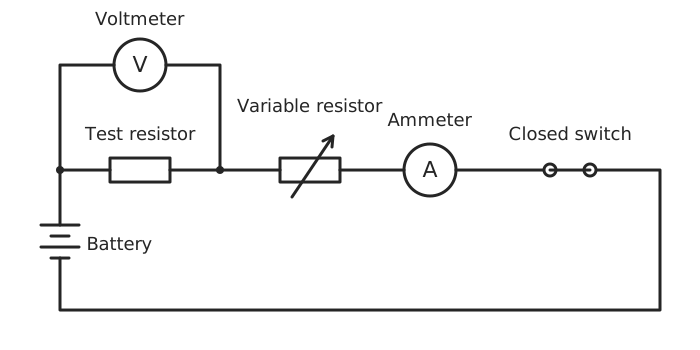
The ammeter measures current through the test resistor; the voltmeter measures potential difference across it. The variable resistor adjusts the electrical conditions.
The resistor shown can be replaced by a test wire, filament lamp, diode, NTC thermistor or LDR. Keep the voltmeter connected directly across whichever component is being investigated: measuring across both that component and the variable resistor would give the wrong potential difference for calculating its resistance.
Before switching on, check the connections and start with a low supply setting and a high variable-resistor resistance. Use suitable meter ranges and stay within the component’s ratings. Low supply voltage alone does not prevent a large current if the resistance is very small.
To compare several test wires, connect each one in turn in the same measuring circuit. Keep the other connecting wires unchanged and their resistance small compared with that of the test wire.
For each wire, adjust the circuit to obtain several different potential differences. Record the potential difference across the wire and its current at each setting, then calculate .
A fair comparison changes only the chosen property. For example, when testing the effect of wire length, use the same material and thickness and change only the length connected into the circuit. Keep temperature as constant as possible: switch off between measurements and allow the wire to cool before taking the next set of readings. A hot wire may have a different resistance, obscuring the effect you intended to investigate.
At the same potential difference, a wire carrying less current has a greater resistance. A graph of current against potential difference also allows the wires’ results to be compared.
Replace the test wire with a filament lamp. Increase the potential difference across it in small steps, recording both meter readings at each step. Wait for the readings to settle before recording them, and calculate the resistance at each setting.
Here, the filament becoming hotter as the current increases is part of the effect being investigated. Its resistance increases as it heats up, so increasing potential difference does not produce a proportional increase in current. The calculated resistances reveal this change.
Do not exceed the lamp’s rating. Disconnect the circuit between sets of measurements and allow the lamp to cool before handling it or repeating the investigation from its starting condition.
A diode allows current to flow readily in one direction but has a very high resistance in the opposite direction. Its orientation therefore matters.
Use the measuring circuit with a series variable resistor to limit the current. Starting at a low setting, vary the potential difference and record paired current and potential-difference readings. Take closely spaced readings where the current starts to rise rapidly.
Switch off, reverse the diode, and repeat within its permitted ratings. This tests the opposite direction, in which the current is normally negligible. If the measured current is zero, do not divide by zero to calculate a resistance; the result shows that the diode strongly opposes current in that direction.
Record the orientation clearly. When presenting both directions on one current–potential difference graph, readings taken in the reverse direction are assigned negative potential difference and current relative to the original direction.
An NTC thermistor is a temperature-sensitive resistor whose resistance decreases as temperature increases. To investigate it, change the temperature rather than deliberately changing the electrical conditions.
Place a suitable thermistor in a water bath with a thermometer. Keep the supply setting unchanged and use a small measuring current to limit heating caused by the circuit itself. Record the temperature, potential difference across the thermistor and current through it.
Begin with cold water, then add warm water gradually and stir gently. At each chosen temperature, wait until the thermometer and meter readings are steady before recording them. This gives the thermistor time to reach the water’s temperature. Calculate its resistance at each temperature and plot resistance against temperature. The resistance should decrease as the water becomes warmer.
Keep the power supply and meters away from water, prevent spills onto electrical connections and use a thermistor suitable for immersion. Handle warm water carefully to avoid scalding.
An LDR, or light-dependent resistor, has a lower resistance in brighter light. Put it in the measuring circuit and keep the supply setting unchanged while changing the light falling on it.
One method is to use an adjustable lamp at a fixed distance. Another is to keep the lamp’s brightness constant and move it to several measured distances from the LDR. Keep the lamp’s direction and background lighting unchanged.
At each setting, wait for steady meter readings, record current and potential difference, and calculate resistance. Brighter illumination should give a lower resistance. Keep the lamp close enough to illuminate the LDR but not touching it, and avoid heating the LDR: the intended change is light, not temperature.
If you measure lamp distance, plot resistance against distance. If you measure light intensity, plot resistance against light intensity. Distance provides a way to change illumination, but it is not itself a light-intensity reading.
For each investigation, use a table with headings and units for the changed quantity, potential difference, current and calculated resistance. Collect enough settings to reveal a trend, repeat measurements under the same conditions and calculate means where appropriate.
A reading is ready to record when the meters are steady and the intended conditions have been reached. If results differ between repeats, check connections and consider whether temperature or lighting has changed.
Wires and lamps can become hot. Do not touch them while the circuit is operating, allow them to cool before handling, and switch off immediately if there is a smell of burning. These precautions also help prevent unintended heating from distorting the investigation.
Units: in volts, in amperes, in ohms.
| Component | Deliberate change | Key result or control |
|---|---|---|
| Wire | Wire tested, or its length; vary p.d. for each wire | Control temperature; for a length test, keep material and thickness unchanged. |
| Filament lamp | Potential difference | Greater current heats the filament and increases resistance. |
| Diode | Potential difference and direction | Limit current; reverse the diode with the supply off. Reverse current is normally negligible. |
| NTC thermistor |
Wait for steady readings, repeat measurements and use labelled tables and graphs. Switch off between measurements where heating is unwanted; allow hot components to cool before handling. Keep water away from the supply and meters.
Draw the ammeter in series and the voltmeter in parallel across the test component only.
State what you change, what you measure and what you keep constant. ‘Take readings’ alone does not explain an investigation.
Use the measured potential difference across the component in R = V/I, not automatically the power supply setting.
Lamp distance is not a measurement of light intensity. Label a graph with the quantity actually measured.
For an NTC thermistor or LDR investigation, limit heating caused by the measuring current so that it does not become an unwanted variable.
It can see this note and what your specification asks for.
Answers are free with an account.
1 free note left this week
Get more free notesYour answer sets when this note comes back for review, or marks it complete.
Was this note helpful?
Log in to tell us whether it helped, or to report a problem.
Last updated
Resistance
Opposition to the flow of electric current, calculated using and measured in ohms ().
Ammeter
An instrument that measures electric current in amperes (A). It is connected in series with the component being tested.
Voltmeter
An instrument that measures potential difference in volts (V). It is connected in parallel across the component being tested.
Variable resistor
A resistor whose resistance can be adjusted to change the current in a circuit.
NTC thermistor
A temperature-sensitive resistor with a negative temperature coefficient: its resistance decreases as its temperature increases.
LDR
A light-dependent resistor whose resistance decreases as the light intensity falling on it increases.
Put your knowledge into practice — try past paper questions for Combined Science A
Resistance
Opposition to the flow of electric current, calculated using and measured in ohms ().
Ammeter
An instrument that measures electric current in amperes (A). It is connected in series with the component being tested.
Voltmeter
An instrument that measures potential difference in volts (V). It is connected in parallel across the component being tested.
Variable resistor
A resistor whose resistance can be adjusted to change the current in a circuit.
NTC thermistor
A temperature-sensitive resistor with a negative temperature coefficient: its resistance decreases as its temperature increases.
LDR
A light-dependent resistor whose resistance decreases as the light intensity falling on it increases.
| Temperature |
| Measure temperature; resistance decreases as temperature rises. |
| LDR | Illumination | Control background light and heating; resistance decreases in brighter light. |