

Loading…
Loading…
Loading…
Edexcel GCSE Design and Technology · 1DT0
Edexcel 1DT0 · 5.2.5 Physical Characteristics of Components Check the specification (PDF) (opens in a new tab)
Electronic components must be selected to suit the circuit, not simply because they fit on the circuit board. Three descriptions help you decide whether a component is suitable: its value, its tolerance and its rating.
A component’s value describes an electrical property. For a resistor, this is its resistance: how strongly it opposes electric current. Resistors can limit current, for example when connected in series with a light-emitting diode (LED). Resistance is measured in ohms, Ω. Larger values commonly use kilohms or megohms:
The marked value is the nominal value. Manufacturing does not produce every component with exactly the same value, so the tolerance tells you the permitted variation. A rating describes an operating limit, such as how much power a resistor can safely dissipate. A resistor can have the correct resistance but still be unsuitable because its power rating is too low.
Many resistors are too small to carry a clearly printed resistance, so coloured bands identify their value. On a four-band resistor, the first two bands give two digits, the third is a multiplier and the fourth gives the tolerance. Identify the tolerance band before reading; a gold or silver tolerance band belongs at the end.
| Colour | Digit | Multiplier |
|---|---|---|
| Black | 0 | ×1 |
| Brown | 1 | ×10 |
| Red | 2 | ×100 |
| Orange | 3 | ×1,000 |
| Yellow | 4 | ×10,000 |
| Green | 5 | ×100,000 |
| Blue | 6 | ×1,000,000 |
| Violet | 7 | ×10,000,000 |
| Grey | 8 | ×100,000,000 |
| White | 9 | ×1,000,000,000 |
| Gold | — | ×0.1 |
| Silver | — | ×0.01 |
Combine the first two digits into one number, then multiply it by the third band’s multiplier. For black through white, the multiplier adds the corresponding number of zeros. Gold and silver multipliers allow small resistances, including values below 10 Ω.
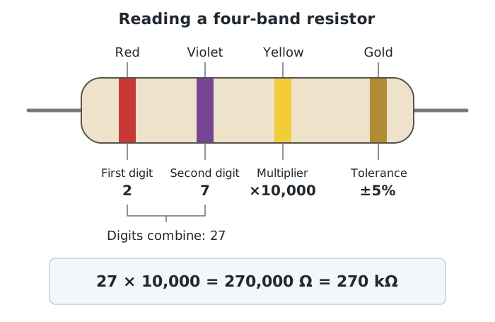
The first two bands give the digits, the third gives the multiplier and the fourth gives the tolerance.
For the resistor shown, red and violet give 27, and yellow means multiply by 10,000. Its nominal resistance is therefore , or 270 kΩ. Gold in the fourth position means ±5% tolerance; it does not change the nominal resistance.
Position matters. Red–violet–gold–gold would instead represent , also with ±5% tolerance. The first gold band is a multiplier; the second is the tolerance.
The fourth band uses a separate tolerance code:
| Tolerance band | Permitted variation |
|---|---|
| Brown | ±1% |
| Red | ±2% |
| Gold | ±5% |
| Silver | ±10% |
| No fourth band | ±20% |
A 390 Ω resistor with ±10% tolerance may have an actual resistance above or below 390 Ω. Ten per cent of 390 Ω is 39 Ω, so its permitted range is:
to .
A smaller percentage gives a tighter range. This matters when a circuit’s behaviour depends on an accurately controlled resistance. A wider tolerance may be acceptable where that variation will not prevent the circuit from working as intended. Select the tolerance to suit the required performance rather than assuming every component must have the tightest possible tolerance.
When current flows through a resistor, electrical energy is transferred to heat. Its power rating, measured in watts, tells you how much power it is designed to dissipate safely under specified conditions. Common small resistors have ratings such as 0.25 W or 0.5 W. Two resistors can have the same resistance but different power ratings.
The power dissipated can be calculated using either:
Here, is power in watts, is the voltage across the resistor in volts, is the current through it in amperes and is its resistance in ohms.
For example, a 27 Ω resistor with 10 V across it dissipates . A 0.25 W resistor is unsuitable even though its resistance might be correct. A resistor rated at 5 W or more can accommodate this power. Exceeding the rating can cause overheating and component failure.
A capacitor stores electric charge. Its value is its capacitance, measured in farads, although electronic components commonly use much smaller units such as microfarads (µF), nanofarads (nF) and picofarads (pF).
Electrolytic capacitors commonly have their capacitance and voltage rating printed on their bodies. A marking of 10 µF, 25 V means that 10 µF is the nominal capacitance and 25 V is the voltage rating. It does not mean that the capacitor needs a 25 V supply. Select a voltage rating greater than the voltage it will experience in the circuit.
Electrolytic capacitors are also polarised: their positive and negative connections must be the correct way round. Check the polarity markings before applying power, because reversing an electrolytic capacitor can cause it to fail dangerously.
Component selection therefore involves several checks together: the value must produce the intended circuit behaviour, the tolerance must allow acceptable variation, and the rating must safely accommodate the operating conditions.
Digit → digit → multiplier → tolerance
Digits: black 0, brown 1, red 2, orange 3, yellow 4, green 5, blue 6, violet 7, grey 8, white 9.
Multipliers: black ×1, brown ×10, red ×100, continuing by powers of ten. Gold ×0.1; silver ×0.01.
Tolerance: brown ±1%, red ±2%, gold ±5%, silver ±10%; no fourth band ±20%.
; .
For a four-band resistor, read two digits, then the multiplier, then the tolerance. The third band is not a third digit.
Gold and silver have different meanings depending on their position: they can be multipliers or tolerance bands.
Calculate tolerance from the nominal value, then subtract and add that amount to find the permitted range.
Distinguish a component’s value from its rating: resistance in Ω is not the same as power rating in W.
Justify component selection by comparing its value, tolerance and rating with the circuit’s requirements.
It can see this note and what your specification asks for.
Answers are free with an account.
1 free note left this week
Get more free notesYour answer sets when this note comes back for review, or marks it complete.
Was this note helpful?
Log in to tell us whether it helped, or to report a problem.
Last updated
Component value
The stated electrical quantity that describes a component, such as a resistor’s resistance or a capacitor’s capacitance.
Nominal value
The stated value of a component, around which its actual value may vary within the specified tolerance.
Tolerance
The permitted variation from a component’s nominal value, usually expressed as a percentage.
Rating
A specified operating limit for a component, such as the maximum voltage or power it can safely withstand under stated conditions.
Resistance
The opposition to electric current, measured in ohms (Ω).
Resistor colour code
A system of coloured bands that identifies a resistor’s nominal resistance and tolerance.
Power rating
The maximum power a component is designed to dissipate safely under specified conditions, measured in watts (W).
Capacitance
A measure of how much electric charge a capacitor stores for a given voltage, measured in farads (F).
Put your knowledge into practice — try past paper questions for Design and Technology
Component value
The stated electrical quantity that describes a component, such as a resistor’s resistance or a capacitor’s capacitance.
Nominal value
The stated value of a component, around which its actual value may vary within the specified tolerance.
Tolerance
The permitted variation from a component’s nominal value, usually expressed as a percentage.
Rating
A specified operating limit for a component, such as the maximum voltage or power it can safely withstand under stated conditions.
Resistance
The opposition to electric current, measured in ohms (Ω).
Resistor colour code
A system of coloured bands that identifies a resistor’s nominal resistance and tolerance.
Power rating
The maximum power a component is designed to dissipate safely under specified conditions, measured in watts (W).
Capacitance
A measure of how much electric charge a capacitor stores for a given voltage, measured in farads (F).